Docking points
The docking points of the PythonPart can be used to connect other Allplan objects with these points. A good example are the associative dimension lines.
Depending on the dynamic state of the PythonPart elements, the docking points are created differently.
Static PythonPart
In a PythonPart, in which:
- the geometry element count and order are static AND
- the point count and order inside the geometry elements is static
the docking points are generated automatically from the geometry elements of the PythonPart without further action needed.
Dynamic element count
In a PythonPart, in which:
- the geometry element count and order are dynamic AND
- the point count and order inside the geometry elements is static
The docking points must be made unique. To do it, a docking point key must be assigned to each model element of the PythonPart. This must be implemented in the script using the SetDockingPointsKey method:
polyhedron_element = AllplanBasisEle.ModelElement3D(com_prop, polyhed)

polyhedron_element.SetDockingPointsKey("Polyhed")
The docking point keys should be assigned in a way that the elements, whose points can be used for meaningful dimension lines, always become the same key.
Example
In the following example, a PythonPart is created with a dynamic count of polyhedrons.
The docking point keys are created from the left and right side, meaning that the
far-left and far-right polyhedrons always become the same docking point key,
the L0 and R0 respectively. The objects next to them become the keys
L1 and R1 respectively and so one...
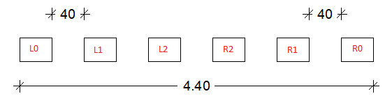
This results in last polyhedrons having the same docking point key, regardless of the total number of the polyhedrons. This makes it possible to place an associative dimension line from the far-left to the far-right polyhedron, which will remain after changing the count of polyhedrons:
Dynamic PythonPart
In a PythonPart, in which:
- the geometry element count and order are dynamic AND
- the point count and order inside the geometry elements is dynamic
The function create_docking_points must be implemented in the script. This function must be used only for creating the docking points of the dynamic elements. For the creation of the docking points of the other elements, only the docking point key must be set.
A template script for creating a standard PythonPart
create_docking_points(build_ele, doc)
Creation of the docking points
Parameters:
| Name | Type | Description | Default |
|---|---|---|---|
build_ele
|
BuildingElement
|
building element with the parameter properties |
required |
doc
|
DocumentAdapter
|
document of the Allplan drawing files |
required |
Returns:
| Type | Description |
|---|---|
List[Tuple[str, Point3D]]
|
list of tuples (key, docking_point) for the 2D view |
List[Tuple[str, Point3D]]
|
list of tuples (key, docking_point) for the 3D view |
List[Tuple[str, Point3D]]
|
list of tuples (key, docking_point) for the 2D and 3D view |
Source code in src\PythonPartsScriptTemplates\StandardPythonPart.py
Example
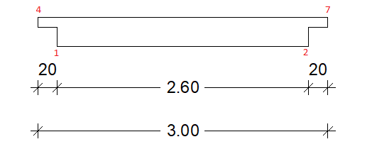
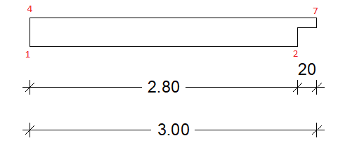
The following example shows a PythonPart element with possible recesses at the left and right side. The docking point keys are represented by a unique name of the element and the point index, as shown below. The number of docking points is reduced to the docking points that are still present in the case where a recess is missing. This allows to adjust the dimension lines in case of a missing recess:
Example
The complete example of creating docking points is implemented in the PythonPart DockingPoints located here:
- …\etc\Examples\PythonParts\BasisExamples\General\DockingPoints.pyp
- …\etc\PythonPartsExampleScripts\BasisExamples\General\DockingPoints.py
To evaluate the functionality of the docking points, the following steps can be performed:
- start Allplan and create a DockingPoints PythonPart
- create associative dimension lines by using the docking points from the PythonPart
- change the created PythonPart by modifying the size, number of elements or by disabling the recesses
- see, how the associative dimension lines are adjusted