Reinforcement placement
Class overview
There are several types of reinforcement placement types in Allplan, which are all represented by different classes in the API. The table below presents an overview of the most relevant ones.
| Placement type | Scheme | Class to use | Remarks |
|---|---|---|---|
| Single | BarPlacement | ||
| Linear |  |
BarPlacement | |
| Polygonal |  |
BarPlacement | Use the appropriate __init__() function with start bending shape and end bending shape |
| Radial |  |
BarPlacement | Use the appropriate __init__() function with rotation axis and angle |
| Circumferential |  |
CircularAreaElement | |
| Areal |  |
BarAreaPlacementService | It's only a helper delivering data for BarPlacement object |
| Extrude along path | 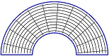 |
ExtrudeBarPlacement | |
| Sweep along path | 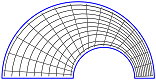 |
SweepBarPlacement |
The diagram below shows the relationships between the classes relevant for creation of rebar placement.
classDiagram
direction BT

class AllplanElement{
    <<Abstract>>
    +CommonProperties CommonProperties
    +Attributes Attributes
}
class ReinfElement{
    <<Abstract>>
}
class BarPlacement{
    int positionNumber
    BendingShape BendingShape
    BendingShape EndBendingShape
    Matrix3D BendingShapeMatrix
    Point3D StartPoint
    Point3D EndPoint
    Vector3D DistanceVector
    Line3D RotationAxis

    GetBarCount() int
    SetLabel()
}
class ExtrudeBarPlacement{
    int PositionNumber
    Path3D path
    float crossBarDistance

    AddCrossBendingShape()
    AddLongitudinalBarProp()
    AddPlacementSection()
    Extrude()
}
class SweepBarPlacement{
    int PositionNumber
    Path3DList paths
    float crossBarDistance

    AddSectionBars()
    AddPlacementSection()
    Sweep()
}
class CircularAreaElement{
    int positionNumber
    int steelGrade
    Line3D RotationAxis
    Polyline3D contourPoints
    float outerAngleStart
    float outerAngleEnd
    float innerAngleStart
    float innerAngleEnd

    SetOverlap()
    SetBarProperties()
}
class LongitudinalBarProperties{
    BendingShape shape
    float overlappingLength
    float startLength
}
class LinearBarPlacementBuilder{
    <<Module>>
    create_linear_bar_placement_from_to_by_dist()
    create_linear_bar_placement_from_to_by_count()
    create_linear_bar_placement_from_by_dist_count()
}
class BarShapePlacementUtil{
    <<Utility>>
    add_shape()
    get_placement_in_corner()
    get_placement_in_side_corners()
    get_placement_in_side_intersection()
    get_placement_at_shape_side_intersection()
}
class BarAreaPlacementService{
    AddOpeningPolygon()
    Calculate()
    SetOuterPolygon()
}
class BarPlacementSection{
    float Length
    float Distance
    bool IsEnabled
}
class BendingShape

ReinfElement --|> AllplanElement
BarPlacement --|> ReinfElement
SweepBarPlacement --|> ReinfElement
ExtrudeBarPlacement --|> ReinfElement

BarAreaPlacementService .. LinearBarPlacementBuilder: delivers data
BarShapePlacementUtil .. LinearBarPlacementBuilder: delivers data
BendingShape "*" --o SweepBarPlacement
LongitudinalBarProperties "*" --o SweepBarPlacement
LongitudinalBarProperties "*" --o ExtrudeBarPlacement
LinearBarPlacementBuilder --> BarPlacement: creates
BendingShape "1-2" --o BarPlacement
BendingShape "1" --o LongitudinalBarProperties
BarPlacementSection "0-4" --o ExtrudeBarPlacement
BarPlacementSection "0-4" --o SweepBarPlacement
BendingShape "*" --o ExtrudeBarPlacement
CircularAreaElement --|> ReinfElement
Single Placement
To place a single rebar, we can use the BarPlacement
class directly, without any helper classes. By simply providing 1 into the barCount argument
and empty or zero objects in all other arguments, we place the rebar shape 1x time. Here is a very
simple example:
placement = AllplanReinforcement.BarPlacement(
    positionNumber = 1,
    barCount       = 1,
    distVec        = AllplanGeo.Vector3D(),
    startPnt       = AllplanGeo.Point3D(), #(1)!
    endPnt         = AllplanGeo.Point3D(),
    bendingShape   = bending_shape)
- Because we provided
1as barCount argument, we can provide zero points and zero vectors to all the arguments relevant for a linear placement.
Info
In a placement defined like this, the rebar will be placed exactly there, where the shape was defined (local system = global system). To place the rebar elsewhere, the BendingShape must be transformed before defining the placement by using one of its transformation methods: Move, Rotate or Transform.
Linear placement
Regular, linear placement of the bar along a given direction and at a given spacing is represented also by the BarPlacement class. However, we recommend using helper methods provided in the LinearBarPlacementBuilder module to create the placement.
Example
Let's create a BarPlacement of a stirrup, that is defined
in YZ plane and saved in stirrup_shape variable. The placement should be linear along the X axis, as shown on
the image to the right. Beside that, we assume following:
- the placement starts in (0,0,0)
- the placement length is 1 m
- the concrete cover is set to 30 mm on all sides
To place the stirrups in a fixed spacing (in our case 15 cm), we can use the function create_linear_bar_placement_from_to_by_dist as follows:
placement = LinearBarPlacementBuilder.create_linear_bar_placement_from_to_by_dist(
    position             = 1,
    shape                = stirrup_shape,  #(1)!
    from_point           = AllplanGeometry.Point3D(   0, 0, 0), #(2)!
    to_point             = AllplanGeometry.Point3D(1000, 0, 0),
    concrete_cover_left  = 30,
    concrete_cover_right = 30,
    bar_distance         = 150,
    start_end_rule       = LinearBarPlacementBuilder.StartEndPlacementRule.AdditionalCover #(4)!
    global_move          = True) #(3)!
-
The shape must already be rotated and aligned with the YZ plane. Refer to this article to learn how to do it
-
Here is a short scheme explaining the meaning of the points, cover and spacing.
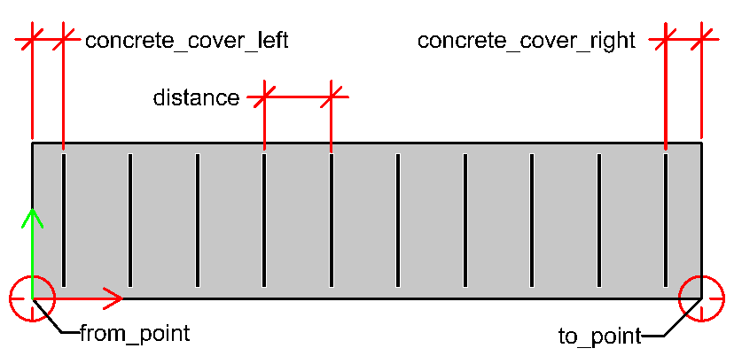
-
This argument is optional and by default set to True. When set to True, the BendingShape will be moved so that the origin of its local coordinate system will be at the point defined in
from_pointargument. -
Here we can set, what should happen, if the placement length is not an exact multiple of spacing. This argument is optional and by default, the distance is preserved and the concrete covers at the start and end are adapted.
To place a fixed count of stirrups (in our case 10 pcs), we can use the function create_linear_bar_placement_from_to_by_count as follows:
placement = LinearBarBuilder.create_linear_bar_placement_from_to_by_count(
    position             = 1,
    shape                = stirrup_shape,  #(1)!
    from_point           = AllplanGeometry.Point3D(   0, 0, 0), #(2)!
    to_point             = AllplanGeometry.Point3D(1000, 0, 0),
    concrete_cover_left  = 30,
    concrete_cover_right = 30,
    bar_count            = 10)
-
The shape must already be rotated and aligned with the YZ plane. Refer to this article to learn how to do it
-
Here is a short scheme explaining the meaning of the points, cover and spacing.
The full implementation of the both functions of the LinearBarPlacementBuilder module mentioned above is shown in the BarPlacement example. The stirrups are placed by distance, and the bottom and top longitudinal bars are placed by count. The example is located in:
- …\etc\Examples\PythonParts\ReinforcementExamples\BarPlacement\BarPlacement.pyp
- …\etc\PythonPartsExampleScripts\ReinforcementExamples\BarPlacement\BarPlacement.py
Polygonal placement
Polygonal placement is a special type of placement in Allplan, but in API it is represented by the same BarPlacement class, that represents a regular linear placement. We simply use different constructor, which requires a start and end shape. The placement is created by Allplan by copying the start shape towards the end shape in combination with linear interpolation of the shape. The shape is placed defined number of times (placement by distance is not possible).
Warning
The start and end shape must consist of the same number of legs!
Example
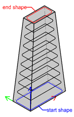
To create a polygonal placement as shown on the image above, we have to create two BengingShapes:
start_shapecontaining the larger stirrup at the bottomend_shapecontaining the bigger stirrup at the top
Both shapes has to be transformed to the desired position in the global coordinate system. To learn more about creating a bending shape, refer to this article. Assuming, the placement should consist of 10 stirrups, the construction is as follows:
placement = AllplanReinf.BarPlacement(positionNumber    = 1,
                                      barCount          = 10,
                                      startBendingShape = start_shape,
                                      endBendingShape   = end_shape)
The full implementation is shown in the PolygonalPlacement example, located in:
- …\etc\Examples\PythonParts\ReinforcementExamples\BarPlacement\PolygonalPlacement.pyp
- …\etc\PythonPartsExampleScripts\ReinforcementExamples\BarPlacement\PolygonalPlacement.py
Placing in regions
In long concrete elements, like beams or columns, the stirrups are often placed along a single line, but the spacing and diameter of the rebars varies along the line, as shown on the image below. Each of these regions with different spacings/diameters must be an individual BarPlacement.
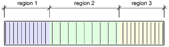
The function calculate_length_of_regions can help create them, by calculating the start and end points of each of the placement. These points can be then used by the function create_linear_bar_placement_from_to_by_dist to create the BarPlacements.
Example
First, we have to define the regions as a list of tuples like this:
- One tuple represents one region. We provide: the region length, spacing and diameter of the rebars respectively.
-
Note, that the length of at least one region must be set to 0! Its length will be then calculated automatically to fill the entire space between start and end point with stirrups. If we provide non-zero lengths in all regions, the result might not be, as we expect.
In this case, the first and last regions are 1 m long and the middle one is calculated.
Now we can calculate the start and end points of each region, using the function calculate_length_of_regions:
region_start_end_points = LinearBarBuilder.calculate_length_of_regions( #(1)!
    value_list           = placement_regions,
    from_point           = AllplanGeo.Point3D(0   , 0, 0),
    to_point             = AllplanGeo.Point3D(4000, 0, 0),
    concrete_cover_left  = 30,
    concrete_cover_right = 30)
- The returned value is a list with tuples (start point, end point).
We can now introduce the final step: creating the placements. We will use the calculated start and end points:
placements: list[AllplanReinf.BarPlacement]: = []

for idx, start_end_point in enumerate(region_start_end_points):
    region_start_point, region_end_point = start_end_point

    placements.append(LinearBarBuilder.create_linear_bar_placement_from_to_by_dist(
        position             = idx + 1, #(1)!
        shape                = shapes[idx], #(2)!
        from_point           = region_start_point,
        to_point             = region_end_point,
        concrete_cover_left  = 0,  #(3)!
        concrete_cover_right = 0,
        bar_distance         = placement_regions[idx][1])) #(4)!
- The
idxwill start by 0, but the first stirrup placement must become the mark number 1 - As we want to place stirrups with different diameters in each region (and a diameter is a property of the shape) we have had to create a list with shapes. To learn, how to create a single stirrup shape, refer to this article. Creating a standard python list with several shapes is straight forward, so we don't show it in this article.
- The function calculate_length_of_regions already takes the concrete covers into account! To avoid considering them two times, we set 0 here.
- The spacing for each placement can be read directly from the list
placement_regions, that we have defined at the very beginning
The full implementation is shown in the example BarPlacementInRegions, located in:
- …\etc\Examples\PythonParts\ReinforcementExamples\BarPlacement\BarPlacementInRegions.pyp
- …\etc\PythonPartsExampleScripts\ReinforcementExamples\BarPlacement\BarPlacementInRegions.py
Placing longitudinal bars
Longitudinal rebars are rarely placed individually based on coordinates of the global coordinate system. Most likely, the placement is defined in relation to some already defined bending shapes. E.g., a longitudinal bar is placed individually in each corner of a stirrup. PythonParts framework offers a helper class BarShapePlacementUtil to calculate the placement points (or lines) for most common cases, listed in the table below.
| Description | Scheme | Method to use |
|---|---|---|
| Place a bar in a stirrup corner | 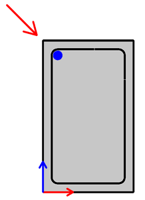 |
get_placement_in_corner |
| Place bars along a stirrup leg | 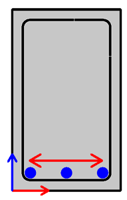 |
get_placement_in_side_corners |
| Place a bar at intersection of two legs | 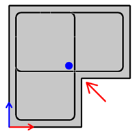 |
get_placement_in_side_intersection |
| Place bars along a stirrup leg, but between two other legs | 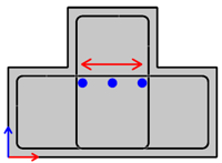 |
get_placement_at_shape_side_intersection |
Warning
Note, that all the reference stirrup shapes have to be flat. The BarShapePlacementUtil calculates the placement points and lines in a two-dimensional, local coordinate system of the stirrup shapes. Thus, the returned points and lined are 2D objects.
Abstract
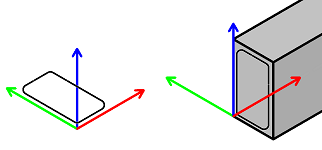
In the following examples we assume, that:
-
The stirrup shapes are defined in the XZ plane. This means, that the RotationAngles object transforming from global to local coordinate system of the stirrups, is defined like this:
-
The longitudinal bar is a straight bar defined along the Y axis. Its axis coincides with the Y axis and its shape definition is saved in the
longitudinal_shapevariable.
Place in corner
To place a longitudinal bar in the corner of a stirrup, we firstly create the BarShapePlacementUtil object, by appending the reference stirrup to it:
- Assigning a meaningful ID to the stirrup shapes (here a string-ID: "stirrup") is important, if we have multiple of them. Here, we only have one.
Now we can call the method
get_placement_in_corner
on the placement_util to get the placement point for the longitudinal bar.
local_placement_pnt = place_util.get_placement_in_corner(
    shape_id           = "stirrup",  #(1)!
    corner_number      = 2,          #(2)!
    placement_diameter = longitudinal_shape.GetDiameter(),
    local_angles       = global_to_local) #(3)!
- We refer to the appropriate stirrup shape by providing its ID here. We defined the ID of each stirrup in the first step, by instantiation of the BarShapePlacementUtil
-
Here we refer to the corner of the stirrup shape by providing the number. The numbering of the corners begins with
1. -
As the stirrup shape is defined in global XZ plane, here we must provide the RotationAngles describing the transformation to a local coordinate system of the stirrup.
The local_placement_pnt is calculated in the local coordinate system of the stirrup,
considering the bending roller applied in this corner, diameter of the stirrup and
the diameter of the longitudinal bar. It needs to be transformed back to the global
coordinate system. E.g., like this:
local_to_global      = global_to_local.change_rotation()
global_placement_pnt = local_placement_pnt * local_to_global.get_rotation_matrix() #(1)!
- The get_rotation_matrix returns a transformation matrix
which can directly be applied on the local point with the multiplication operator
*to get the global point. To learn more about transformation matrices, refer to this article
Now, we can move the shape into the position of the placement point in the first step, and place the rebar 1x time in the second step:
longitudinal_shape.Move(AllplanGeo.Vector3D(global_placement_pnt))

placement = AllplanReinforcement.BarPlacement(1, 1,
                                              AllplanGeo.Vector3D(),
                                              AllplanGeo.Point3D(),
                                              AllplanGeo.Point3D(),
                                              longitudinal_shape)
Place on side
To distribute longitudinal bars equally along the entire length of a specified stirrup
leg, we will use the get_placement_in_side_corners
method of the BarShapePlacementUtil.
Creating the place_util looks exactly the same, as in the previous example,
so we jump directly to the calculation of the placement line:
local_placement_line, placement_cover_left, placement_cover_right = \
    place_util.get_placement_in_side_corners(
        shape_id            = "stirrup",
        side_number         = 4,        #(1)!
        placement_diameter  = longitudinal_shape.GetDiameter(),
        local_angles        = global_to_local) #(2)!
-
We refer to a specific stirrup leg by providing its number. The numbering begins with 1. Hooks are also considered as legs.
Failure
The get_placement_in_side_corners calculates the placement line between two bending points. The first leg of a stirrup does not have a bending at its start. Therefore, referring to it will result in an error.
-
As the stirrup shape is defined in the global XZ plane, here we must provide the RotationAngles object describing the transformation to a local coordinate system of the stirrup.
The local_placement_line is a 2D line, calculated in the
local coordinate system of the stirrup. To use it to place the longitudinal bars, it
needs to be transformed back to the global coordinate system:
local_to_global       = global_to_local.change_rotation()
global_placement_line = AllplanGeo.Line3D(local_placement_line)
global_placement_line *= local_to_global.get_rotation_matrix() #(1)!
- We can directly apply the Matrix3D on the local
line using multiplication assignment operator (
*=). To learn more about the usage of transformation matrices, refer to this article
We can now use the global_placement_line, placement_cover_left and placement_cover_right
to create the linear placement of the longitudinal bars. We will use the appropriate
method from the LinearBarPlacementBuilder:
placement = LinearBarPlacementBuilder.create_linear_bar_placement_from_to_by_count(  \
        1,
        longitudinal_shape,
        global_placement_line.StartPoint,
        global_placement_line.EndPoint,
        placement_cover_left,
        placement_cover_right,
        3) #(1)!
- At this step we can define, how many bars we want to place.
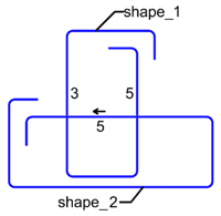
Place at legs intersection
The BarShapePlacementUtil can calculate a placement point for a longitudinal bar at the intersection of two stirrup legs. The two reference legs can belong to one or two separate stirrups. In this example, we assume two separate rectangular, closed stirrups.
We construct the utility by appending both stirrup shapes to it at the beginning:
place_util = BarShapePlacementUtil()
place_util.add_shape("vertical stirrup", stirrup_shape_1)
place_util.add_shape("horizontal stirrup", stirrup_shape_2)
To calculate the placement point at the intersection of the right leg of the
vertical stirrup and the bottom leg of the horizontal stirrup, we call the method
get_placement_in_side_intersection
on the placement_util as follows
local_placement_pnt = place_util.get_placement_in_side_intersection(
shape_id1 = "vertical stirrup",
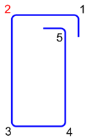
side_number1 = 5, #(1)!
b_above_side1 = True, #(2)!
shape_id2 = "horizontal stirrup",
side_number2 = 3, #(3)!
b_above_side2 = True, #(4)!
placement_diameter = longitudinal_shape.GetDiameter(),
local_angles = global_to_local)
-
The right leg of the vertical stirrup is its 5th one
-
Because we want to place the longitudinal bar at the left side of the leg and the leg's direction points upwards, we must provide True here.
-
The bottom leg of the horizontal stirrup is its 3rd one.
-
Because we want to place the longitudinal bar above this leg, and the leg's direction points to the right, we must provide True here.
The local_placement_pnt is a 2D point calculated in
the local coordinate system of the stirrups. It needs to be converted to a 3D point
and transformed back to the global coordinate system:
local_pnt_3d         = AllplanGeo.Point3D(local_placement_pnt)
local_to_global      = global_to_local.change_rotation()
global_placement_pnt = local_pnt_3d * local_to_global.get_rotation_matrix()
The global_placement_pnt can be used to create a single bar placement exactly the
same way, as we done it in the example of placing longitudinal bar in the corner
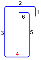
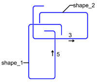
Place on side between two legs
Sometimes we want to place the longitudinal bars on a stirrup leg, but not along its entire length, but between two other legs, as shown on the image to the right. In this example, we will place the longitudinal bars on the top leg of the horizontal stirrup, but between both vertical legs of the vertical stirrup.
First, we construct the utility by appending both stirrup shapes to it:
place_util = BarShapePlacementUtil()
place_util.add_shape("vertical stirrup", stirrup_shape_1)
place_util.add_shape("horizontal stirrup", stirrup_shape_2)
To distribute longitudinal bars on the top leg between the vertical legs, we will use the get_placement_at_shape_side_intersection method of the BarShapePlacementUtil.
local_placement_line, placement_cover_left, placement_cover_right = \
    place_util.get_placement_at_shape_side_intersection(
        shape_id1          = "vertical stirrup",
        side_number1       = 3,     #(1)!
        shape_id2          = "vertical stirrup",
        side_number2       = 5,
        shape_id3          = "horizontal stirrup",
        side_number3       = 5,     #(2)!
        b_above_side3      = True,  #(3)!
        placement_diameter = longitudinal_shape.GetDiameter(),
        local_angles       = global_to_local)
-
The first and second reference legs are the legs limiting the placement from both sides. It does not matter, which is left and which right. In our case, the placement is limited by the 3rd and 5th leg of the vertical stirrup, as shown on the image to the right.
-
The third reference leg is the leg, on which the longitudinal bars will be placed on.
-
We want to place the bars below the leg. But because the legs direction points to the left, we set the argument to True.
As a result we become local_placement_line, placement_cover_left and placement_cover_right
exactly as in the example of placing on side. The transformation back to
the global coordinate system and creation of the placement look therefore exactly the same.
Example
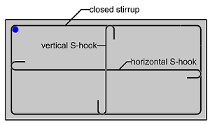
The full implementation of the four, above mentioned methods of the BarShapePlacementUtil is shown in the example LongitudinalBarPlacement. There are three reference shapes defined in the example, as shown in the image to the right. You can experiment with the utility by selecting the placement method, reference shapes and side/corner numbers in the palette.
The example is located in:
- …\etc\Examples\PythonParts\ReinforcementExamples\BarPlacement\LongitudinalBarPlacement.pyp
- …\etc\PythonPartsExampleScripts\ReinforcementExamples\BarPlacement\LongitudinalBarPlacement.py
Radial placement
Radial placement is a special type of placement in Allplan, but in API it is represented by the same class, as a regular linear placement. The difference is, that the BarPlacement is constructed using a different constructor. But the steps, that must be introduced in the code, are the same, as when placing the bar individually: firstly we need to have a BendingShape defined in global coordinate system. For now, there are no helper classes for creating this kind of placement.
Example
Let's place a straight bar defined in bending_shape variable around the Z axis. Assuming,
that the shape is defined along the X axis, let's place it beginning from 0° up to 90°.
We will place the bar 10 times.
delta_angle = AllplanGeo.Angle.FromDeg(-(90 - 0)/(15 - 1)) #(1)!

rotation_axis = AllplanGeo.Line3D(AllplanGeo.Point3D(0, 0, 0),
                                  AllplanGeo.Point3D(0, 0, 1)) #(2)!

placement = AllplanReinf.BarPlacement(positionNumber = 2,
                                      barCount       = 10,
                                      rotationAxis   = rotation_axis,
                                      rotationAngle  = delta_angle,
                                      bendingShape   = bending_shape)
- This is the angle between each rebar. We determine it as the total delta angle
(
end_angle - start_angle) divided by the number of spaces between bars, which isbar_count - 1 - The rotation axis is defined in the Z+ direction
Bug
For the moment, the placement rotation is not created according to the right hand placement rule. Therefore, we the delta angle is negative although, according to the rule, it should be positive, as the rotation axis is pointing in the Z+ direction.
The full implementation is shown in the example CircularArea, located in:
- …\etc\Examples\PythonParts\ReinforcementExamples\BarPlacement\CircularArea.pyp
- …\etc\PythonPartsExampleScripts\ReinforcementExamples\BarPlacement\CircularArea.py
Circular placement
A circular rebar placement is a special type of placement in Allplan, represented by a special class CircularAreaElement. This kind of placement does not require BendingShape to be defined beforehand. This makes this placement very specific: it can generate rebars with only one curvature. No additional bents, like hooks, bent-offs, etc. are possible.
The placement is defined by rotating a contour (3D polyline) around the rotation axis. On the surface thus created (let's call it reference surface), along its circumferential direction, rebars are placed as rings parallel to each other. The rebars can be extended beyond the reference surface in order to overlap with reinforcement of adjacent elements.
Example
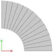
Let's create a circular placement on a reference surface in XY plane, shaped as a 90° section of an annulus, as shown on the image above. The assumptions are:
- inner and outer radius of 2 and 5 m respectively
- start and end angle of 0° and 90° respectively
- 10 mm rebars are placed in a 20 cm spacing
- all concrete covers are set to 30 mm
The contour would be a simple line, starting at the inner radius and ending
by the outer radius. The rotation_axis is a simple line pointing in Z+ direction:
contour = AllplanGeo.Polyline3D()
contour += AllplanGeo.Point3D(2000, 0, 0)
contour += AllplanGeo.Point3D(5000, 0, 0)

rotation_axis = AllplanGeo.Line3D(AllplanGeo.Point3D(0, 0, 0),
                                  AllplanGeo.Point3D(0, 0, 1))
To get a valid CircularAreaElement, we must introduce at least three steps.
-
First, we construct the CircularAreaElement object. Then, we set the rebar properties and at last the overlapping
circular_area = AllplanReinf.CircularAreaElement( positionNumber = 1, diameter = 10, steelGrade = -1, #(1)! concreteGrade = -1, rotationAxis = rotation_axis, contourPoints = contour, outerAngleStart = 0, outerAngleEnd = 90, innerAngleStart = 0, #(2)! innerAngleEnd = 90, concreteCoverStart = 30, #(3)! concreteCoverEnd = 30, concreteCoverContour = 30) #(4)!- We will use currently set steel and concrete grade
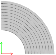
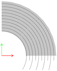
-
The inner and outer arcs result from rotating the start and end point of the
contourrespectively. The start and end angles of both arcs can be set independently. This can result in a placement as shown below.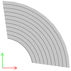
-
The start and end concrete covers are the ones at the inner and outer arcs respectively
-
The contour cover is the cover between rebars and the reference surface. In our case, the reference surface is in the XY plane, so the rebars will be moved 30 mm in Z+ direction.
-
Then, we set the properties relevant for rebars with SetBarProperties
circular_area.SetBarProperties( distance = 200, maxBarLength = 18000, #(1)! minBarLength = 1000, placementRule = 0, #(2)! oddFirstLength = 18000, #(3)! evenFirstLength = 18000, minBarRadius = 0, maxBarRise = 10000) #(4)!- If the maximum length is exceeded, an overlap joint will be created automatically
-
There are following options for placement rules:
Option Value None 0 Skewed 1 Optimized 2 Refer to the Allplan documentation, to learn more.
-
We can set the length of the first rebar in the odd and even rings, so that the rebar overlaps are located evasively
-
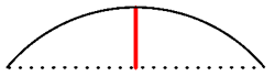
This is the maximum allowed rise of an arc rebar (see red line on the image below). It is usually dictated by transportation constraints. If exceeded, an overlap is introduced.
-
At last we set the overlapping lengths and properties with SetOverlap
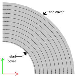
circular_area.SetOverlap( oddOverlapStart = 0, #(1)! evenOverlapStart = 0, bOverlapStartAsCircle = False, oddOverlapEnd = 0, evenOverlapEnd = 0, bOverlapEndAsCircle = False, overlapLength = 0)-
The rebars can be extended beyond the surface at their start and end. The length of this extension can vary in even and odd rebar. The extension can be circular or straight (depending on the
bOverlap____AsCircleargument)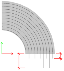
-
The full implementation is shown in the example CircularArea, located in:
- …\etc\Examples\PythonParts\ReinforcementExamples\BarPlacement\CircularArea.pyp
- …\etc\PythonPartsExampleScripts\ReinforcementExamples\BarPlacement\CircularArea.py
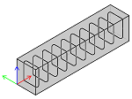
Extrude along path
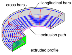
Reinforcement placement can be created as an extrusion along path. It is represented by the ExtrudeBarPlacement class. To construct such object, we need three main elements:
- extrusion path
- bars perpendicular to the extrusion path: cross bars
- bars parallel to the extrusion path: longitudinal bars
Extrusion path
The extrusion path is represented by the Path3D. This object can consist of multiple curves of any type: spline, arc, polyline, etc. All the individual curves together must form one, continuous curve.
spline = AllplanGeo.Spline3D(...)
line = Allplan.Geo.Line3D(...)

path = AllplanGeo.Path3D()
path += spline
path += line  #(1)!
- As the line comes after the spline, the start point of the line must match the end point of the spline!
Cross bars
Cross bars are represented by BendingShape objects defined in the same way, as for a linear placement: as a flat, polygonal shape. The shape must be defined in the global coordinate system, at the start point of the extrusion path. Refer to this article to learn how to define a polygonal shape.
The cross bars can be placed along the path with a fixed spacing defined for the whole placement. However, you can define up to four placement sections with different spacing. First two will be applied at the start, the other two at the end of the placement. These sections are represented by BarPlacementSection class.
placement_section = AllplanReinf.BarPlacementSection(isEnabled  = True,
                                                     length     = 1000,
                                                     distance   = 100) #(1)!
- Adding a placement section, defined like this, to the placement will result in the cross bars being placed every 10 cm over the first 1 m of the placement.
The rotation of the cross bars along the extrusion path is defined using the enumeration class eProfileRotation. The bars can rotate in order to e.g., preserve the angle between the them and the extrusion path.
Longitudinal bars
Each individual longitudinal bar is represented with a LongitudinalBarProperties object. It contains information about:
- position of the longitudinal bar in the extruded profile
- overlapping length
- anchorage at the start and at the end of the placement
- how rebars are delivered: bent or straight
The position of the longitudinal bar is defined in the BendingShape object as a point shape, which is then extruded along the extrusion path to form a longitudinal rebar.
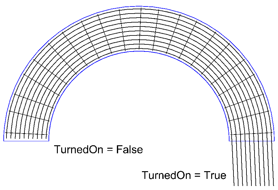
longitudinal_bar = AllplanReinf.LongitudinalBarProperties(
    shape                      = longitudinal_shape, #(1)!
    overlappingAtStartTurnedOn = False, #(2)!
    overlappingAtStart         = 0,
    overlappingAtEndTurnedOn   = False,
    overlappingAtEnd           = 0,
    overlappingLength          = 100, #(3)!
    minBarDistance             = 0,
    deliveryShapeType          = AllplanReinf.LongitudinalBarProperties.eStraight, #(4)!
    insideBarsState            = AllplanReinf.LongitudinalBarProperties.eExact,
    startLength                = 0) #(5)!
- The shape is a BendingShape object, containing a point shape of the longitudinal bar. Refer to this article to learn how to construct it.
-
With this option the longitudinal bar can be extended beyond the extrusion, to create an anchorage:
-
When the length of the longitudinal bar exceeds the maximum bar length set in Allplan options, an overlapping joint is introduced automatically. Here, we can define the length of this overlapping.
- When set to
eStraight, the longitudinal bar (although curves) will be shown as a straight bar on the bending schedule. - You can define the length of the first bar. It becomes relevant, when the overlap joints must be set alternately.
Example
Let's construct an extrusion placement, assuming we already have the following ingredients:
pathwith the extrusion path, which we defined previouslystirrup_shapewith the stirrup shape, defined in the global XZ planeplacement_sectionwhich we defined defined herelongitudinal_bar, which we defined above
We can start with constructing the ExtrudeBarPlacement object:
placement = AllplanReinf.ExtrudeBarPlacement(
    positionNumber         = 1,
    path                   = path,
    profileRotation        = AllplanReinf.ExtrudeBarPlacement.eStandard,
    breakElimination       = False, #(1)!
    maxBreakAngle          = 0,
    crossBarDistance       = 300, #(2)!
    concreteCoverStart     = 25,
    concreteCoverEnd       = 25,
    edgeOffsetType         = AllplanReinf.ExtrudeBarPlacement.eStartEqualEnd, #(3)!
    edgeOffsetStart        = 0,
    edgeOffsetEnd          = 0,
    barOffset              = 0, #(4)!
    bendingShapeViewVector = AllplanGeo.Vector3D(0,1,0)) #(5)!
- Setting this to True would result in breaking up the placement at bends of the path,
where the angle is greater than the value defined in
maxBreakAngle. - The spacing distance is measured on the extrusion path!
- With this setting, the first and the last cross bar will be placed with an equal distance
from the start and end point of the extrusion path. Because we set it like this,
we can assign 0 to the
edgeOffsetStartandedgeOffsetEnd, as they will be calculated automatically. See the documentation of eEdgeOffsetType for all possible options. - This is the offset between the individual cross bars. It becomes relevant, when we have at least two cross bending shapes that (partially) overlap. When set to 0, it will be difficult to tell the bending shapes apart.
- Because we assumed the
stirrup_shapeis defined in XZ plane, the view direction onto it is Y+
Now, we can append all the components to the placement itself:
placement.AddCrossBendingShape(stirrup_shape)
placement.AddLongitudinalBarProp(longitudinal_bar)
placement.AddPlacementSection(placement_section)
At the end, the extrusion must be executed:
The full implementation is shown in the example ExtrudeBarAlongPath, located in:
- …\etc\Examples\PythonParts\ReinforcementExamples\BarPlacement\ExtrudeBarAlongPath.pyp
- …\etc\PythonPartsExampleScripts\ReinforcementExamples\BarPlacement\ExtrudeBarAlongPath.py
Sweep along path
Reinforcement placement can be created by sweeping bending shapes along path. This type of placement is represented by the class SweepBarPlacement and is very similar to extrusion along path, but with the difference, that the reinforced cross-section does not have to be constant along the entire path. Therefore, to define it we need following objects:
- at least one sweeping path
-
at least one cross-section, understood as a set of:
- cross bending shapes, perpendicular to sweeping paths
- longitudinal bending shapes, parallel to sweeping paths
Info
The position of the cross and longitudinal bars may vary along the path, but the amount of them must remain constant! In addition, regarding cross bars: their shape can also vary along the path, but only in the sense of length and bending angles of individual legs. The number of legs must remain constant!
Sweeping path
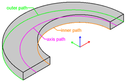
The individual sweeping paths are defined exactly the same, as extrusion path: as Path3D. A sweeping path should be preferably located at the vertices of the cross bending shapes
axis_path  = AllplanGeo.Path3D()
inner_path = AllplanGeo.Path3D()
outer_path = AllplanGeo.Path3D()

axis_path  += axis_spline
inner_path += inner_spline
outer_path += outer_spline
More than one sweeping path can be defined, as shown above. All has to be appended to a single Path3DList:
sweep_paths = AllplanGeo.Path3DList()
sweep_paths.append(axis_path)
sweep_paths.append(inner_path)
sweep_paths.append(outer_path)
Cross sections
An individual cross-section is added to the placement using the AddSectionBars method, and consists of:
-
individual cross bars defined as BendingShapes organized in one BendingShapeList
cross_bars_start = AllplanReinf.BendingShapeList() cross_bars_start.append(bottom_stirrup_start) #(1)! cross_bars_start.append(top_stirrup_start)- The
bottom_stirrup_startandtop_stirrup_startare both BendingShapes defined in the global coordinate system!
- The
-
individual longitudinal bars defined as LongitudinalBarProperties (just as in the extrude placement) organized in one LongitudinalBarPropertiesList
longi_bars_start = AllplanReinf.LongitudinalBarPropertiesList() longi_bar = AllplanReinf.LongitudinalBarProperties(shape, ...) #(1)! longi_bars_start.append(longi_bar)- The definition of an individual longitudinal bar is exactly the same, as for when extruding along path.
-
a plane, on which the bending shapes will be projected
Warning
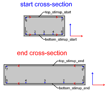
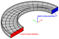
When the sweep placement should consist of more than one cross-sections, the order of the shapes in the list matters!
E.g., if the rebar in the bottom left corner of the start cross-section (number 1 on the image to the right) is the same rebar, as the bottom right one in the end cross-section, they must both be on the same position in the LongitudinalBarPropertiesList
The same applies to the direction of the cross-bars bending shapes, as indicated with the red arrows.
Example
Let's construct a sweep placement, assuming we already have the following ingredients:
sweeping_paths: a list of sweeping paths, which we defined herecross_bars_start: a list of stirrup shapes at the start cross-section, which we defined herecross_bars_end: a similar list, but at the end cross-sectionlongi_bars_start: a list of longitudinal bars at the start cross-section, which we defined herelongi_bars_end: a similar list, but at the end cross-section
We can start with constructing the SweepBarPlacement object:
placement = AllplanReinf.SweepBarPlacement(
    positionNumber           = 1,
    sweepPaths               = sweep_paths,
    rotation                 = True, #(1)!
    firstPathIsSweepPath     = True,
    interpolation            = True, #(2)!
    interpolationOfAllPoints = True,
    crossBarDistance         = 200, #(3)!
    concreteCoverStart       = 25,
    concreteCoverEnd         = 25,
    edgeOffsetType           = AllplanReinf.SweepBarPlacement.eStartEqualEnd, #(4)!
    edgeOffsetStart          = 0,
    edgeOffsetEnd            = 0,
    barOffset                = 0, #(5)!
    benchingLength           = 0, #(6)!
    benchingAngle            = 0)
- Then set to True the cross bars will be rotated, so that the angle between the first sweeping path will be preserved.
- When set to False, only the first path will be considered for all points of the bending shapes.
- The spacing distance is measured on the first sweeping path!
- With this setting, the first and the last cross bar will be placed with an equal distance
from the start and end point of the extrusion path. Because we set it like this,
we can assign 0 to the
edgeOffsetStartandedgeOffsetEnd, as they will be calculated automatically. See the documentation of eEdgeOffsetType for all possible options. - The offset between the individual cross bars. It becomes relevant, when we have at least two cross bending shapes that (partially) overlap. When set to 0, it will be difficult to tell the bending shapes apart.
- Providing
benchingLengthandbenchingAnglegreater than 0 will result in fewer marks of the cross bars.
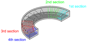
We can now append the cross-sections to the placement using the AddSectionBars. At least one cross-section must be appended to the placement, but there is no upper limitation. In this example, we append only two: the start and end cross-sections.
placement.AddSectionBars(
    bendingShapes                = cross_bars_start,
    sectionsLongitudinalBarsProp = longi_bars_start,
    sectionPlane                 = AllplanGeo.Plane3D(sweep_paths[0].StartPoint,
                                                      AllplanGeo.Vector3D(0, 1, 0)))
placement.AddSectionBars(
    bendingShapes                = cross_bars_end,
    sectionsLongitudinalBarsProp = longi_bars_end,
    sectionPlane                 = AllplanGeo.Plane3D(sweep_paths[0].EndPoint,
                                                      AllplanGeo.Vector3D(0, 1, 0)))
We can optionally append up to four placement sections, as described in this paragraph:
At the end, the sweeping must be executed:
The full implementation is shown in the example SweepBarAlongPath, located in:
- …\etc\Examples\PythonParts\ReinforcementExamples\BarPlacement\SweepBarAlongPath.pyp
- …\etc\PythonPartsExampleScripts\ReinforcementExamples\BarPlacement\SweepBarAlongPath.py