Operations
3D to 2D
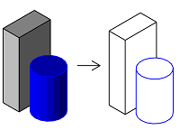
To calculate 2D lines based on a 3D geometry, use the HiddenCalculus class. It uses the so called hidden calculation to calculate two collection of 2D lines:
- visible lines - representing the visible edges of the solids
- hidden lines - representing the edged hidden behind a solid
To perform the calculation, following parameters needs to be specified
- the observer's point of view
- the direction he is looking to
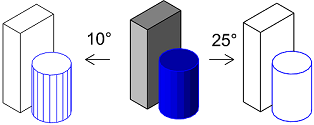
- the boundary angle between adjacent faces of a polyhedron, above which the line representing the edge is drawn
Note
The HiddenCalculus class can calculate 2D lines only out of a polyhedron. A BRep must be tessellated into a polyhedron first. See this chapter to learn how to do it
Let's have a look on an example implementation. Before beginning the calculation, we have to create a HiddenCalculationParameters object with all the parameters and at least one HiddenMaterial object, which we can then assign to each polyhedron individually:
parameters = AllplanGeometry.HiddenCalculationParameters()

parameters.AdjacentEdgesMaxAngle = AllplanGeometry.Angle.FromDeg(10) #(1)!

parameters.SetObserverMatrix(eyePoint=  AllplanGeometry.Point3D( 0, 0, 0),
                             viewPoint= AllplanGeometry.Point3D( 1, 1,-1)) #(2)!

parameters.GetHiddenLines = True #(3)!

material = AllplanGeometry.HiddenMaterial() #(4)!
-
The edges between faces meeting at an angle of higher than 10° will be drawn and below that angle will not. The higher the angle, the less edges are drawn
-
With eye and vew point set like this we will get an isometric view from the front left. Note, that we can only get an isometric view. Perspective is not possible.
-
If we are only interested in visible lines, we can set this option to
False. This will reduce the calculation time. - We can create several HiddenMaterial objects and assign them individually to each polyhedron, that we want to calculate 2D lines from. At the end of the calculation, we can get the material back from each calculated 2D line. In our example, we create just one for all elements.
Now we can construct the actual HiddenCalculus class and perform the calculation:
hidden_calculus = AllplanGeometry.HiddenCalculus()
hidden_calculus.Configure(parameters) #(1)!

hidden_calculus.AddElement(cuboid, material, elementTag = 0)
hidden_calculus.AddElement(cylinder, material, elementTag = 1) #(2)!

hidden_calculus.Calculate()

#getting the results
for i in range(hidden_calc.GetLinesCount()):
    line, result = hidden_calculus.GetResultLine(i) #(3)!
    tag = hidden_calculus.GetResultLineTag(i) #(4)!
- Applying the calculation parameters, that we set earlier
- Each element, in addition to the material, can also be appended a tag (simple integer). This will be hooked to each 2D line, that resulted from this particular polyhedron
-
After the calculation is done, we can get the calculated lines by their index. The
resulttells us, whether the line is a visible or a hidden one. Note, that the returnedlineis a Line3D and has to be converted to 2D line, e.g. like this: -
Using the GetResultLineTag method, we can retrieve the tag from the line, giving us the ability to associate it with the 3D object, from which it resulted. Based on that we can give the line the same attributes or common properties, as the source polyhedron.
Example
The complete implementation of the hidden calculation is available in the PythonPart HiddenCalculus located in:
- …\etc\Examples\PythonParts\GeometryExamples\Operations\Others\HiddenCalculus.pyp
- …\etc\PythonPartsExampleScripts\GeometryExamples\Operations\Others\HiddenCalculus.py
Abstract
Alternatively, you can calculate the visible and hidden edges with the function GroundViewHiddenCalculation. However, this function is much more limited, as we are not able to set an observer matrix, adjust the angle for adjacent faces or append a tag or material on the polyhedron. For that reason, we do not recommend to use it anymore.
Boolean operations
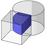
Intersection
To calculate an intersection solid out of two or more solids, use the Intersect function. The intersection can be calculated between two polyhedrons or two BReps or one BRep and one polyhedron.
intersecting, resulting_polyhedron = \
    AllplanGeometry.Intersect(first_polyhedron, second_polyhedron) #(1)!
- The function returns also a bool value
intersectingof True, when the two geometries intersect with each other, making the collision control possible.
Abstract
The geometry module offers also the MakeIntersection function, offering almost the same possibilities. However, to ensure consistency, we recommend using the Intersect function.
Example
The implementation of the function is shown in four examples:
- The IntersectBRepBRep shows the implementation on two BReps
- The IntersectPolyhedronPolyhedron shows the implementation on two polyhedrons
- The IntersectBRepPolyhedron shows the implementation on a polyhedron and a BRep
- The IntersectBRepList shows the implementation of the MakeIntersection function, which is capable of calculating the intersection between a BRep and a list of BReps.
All the examples are located in:
- …\etc\Examples\PythonParts\GeometryExamples\Operations\BooleanOperations\
- …\etc\PythonPartsExampleScripts\GeometryExamples\Operations\BooleanOperations\
Tip
We can also pass two special lists (PolyhedronTypesList), containing various types of geometries, into the Intersect function. The geometries included in the first list will be considered as one polyhedron. The same applies to the second list. The intersection will be then calculated on these two united geometries. Beside polyhedrons, also other type of geometries can be appended to the list. Refer to the documentation, to learn more. The implementation is shown in the example IntersectPairs located in:
- …\etc\Examples\PythonParts\GeometryExamples\Operations\BooleanOperations\IntersectPairs.pyp
- …\etc\PythonPartsExampleScripts\GeometryExamples\Operations\BooleanOperations\IntersectPairs.py
Union
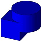
To join several polyhedrons or BReps into one geometry, use the MakeUnion function.
polyhedrons = AllplanGeometry.Polyhedron3DList() #(1)!

polyhedrons.append(first_polyhedron) #(2)!

polyhedrons += [second_polyhedron, third_polyhedron] #(3)!

result, resulting_geo = AllplanGeometry.MakeUnion(polyhedrons) #(4)!
- Construct a list object first
- And append the polyhedrons to unite using either
appendfunction... - ... or the addition assignment operator.
- The
resultcan contain a simple bool value (True for successful operation) or the geometry error code. Refer to the API reference, to see what returns the function you are using in your script.
Warning
You cannot mix polyhedrons with BReps. If you need to join a polyhedron with a BRep, you have to decide, whether to:
- Tessellate all the BReps into polyhedrons, as described in this chapter, or
- Convert all the polyhedrons into BReps using the CreateBRep3D function. In this way, we avoid the loss of information inevitably associated with tessellation.
One cannot arbitrarily say which option is better. Refer to this chapter to learn more about the differences between polyhedrons and BReps.
Example
The implementation of the MakeUnion function is shown in the example UnitePolyhedrons located in:
- …\etc\Examples\PythonParts\GeometryExamples\Operations\BooleanOperations\UnitePolyhedrons.pyp
- …\etc\PythonPartsExampleScripts\GeometryExamples\Operations\BooleanOperations\UnitePolyhedrons.py
Tip
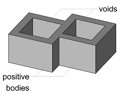
It is possible to perform the union operation using two lists:
- first containing polyhedrons, that are to be considered as positive bodies
- second containing polyhedrons, that are to be considered as voids
The geometries from the first list will be joined into one polyhedron and after that the geometries from the second list will be subtracted. This implementation is shown in the example UnitePolyhedronsWithVoid located in:
- etc\Examples\PythonParts\GeometryExamples\Operations\BooleanOperations\UnitePolyhedronsWithVoid.pyp
- etc\PythonPartsExampleScripts\GeometryExamples\Operations\BooleanOperations\UnitePolyhedronsWithVoid.py
Subtraction
To subtract a solid from another solid (polyhedron or BRep), use the MakeSubtraction function. The first argument of the function is always the solid to subtract from (minuend) and the second one is the one to be subtracted (subtrahend).
To subtract several solids at once, provide a list of them as subtrahend:
subtrahend_polyhedrons = PolyhedronTypesList() #(1)!

subtrahend_polyhedrons += [first_subtrahend,
                           second_subtrahend]

error, resulting_geo = \
    AllplanGeometry.MakeSubtraction(minuend_polyhedron,
                                    subtrahend_polyhedrons)
- Use the special PolyhedronTypesList to ensure that only a valid geometry type will be appended to the list.
Warning
Just as in the case of union, all arguments have to be either polyhedrons or BReps and those two cannot be mixed.
All-in-one
A way to compute all boolean operations possible on two polyhedrons, is to use the MakeBoolean. This functions computes:
- intersection of two polyhedrons
- union of two polyhedrons
- subtraction by subtracting second element from the first one
- subtraction by subtracting first element from the second one
all in one step.
error, intersection, union, subtraction1, subtraction2 = \
    AllplanGeometry.MakeBoolean(first_polyhedron,
                                second_polyhedrons) #(1)
-
The
errorwill contain the error code and the following four elements contain polyhedrons being the result of:- intersection
- union
- subtraction of first polyhedron minus the second one
- subtraction of second polyhedron minus the first one
Example
The implementation of the MakeBoolean function is shown in the example MakeBoolean located in:
- …\etc\Examples\PythonParts\GeometryExamples\Operations\BooleanOperations\MakeBoolean.pyp
- …\etc\PythonPartsExampleScripts\GeometryExamples\Operations\BooleanOperations\MakeBoolean.py
Comparing
Equality
To check whether two geometry objects are equal without tolerance, you can simply use the equal operator:
To be able to set a tolerance when comparing, use one of the following methods:
- Equal: compares objects with an optional tolerance
- EqualRel: also compares objects, but additionally considers the value set in the Allplan settings -> desktop environment -> minimum distance between points. When the distance between the points is below this value, they are considered equal regardless of the tolerance.
method. This method is capable of comparing basic objects, like points or vectors and curves (line, arc, etc.). Although, it is not capable of comparing solids or surfaces directly, it can still compare their vertices, edges or iso-curves.
Warning
The argument tolerance is not the allowed delta between two points to consider them equal, but the value used to calculate delta value! Use very small values here!
Example: Setting the tolerance to 1e-11 mm would mean, that points with coordinates around 1 mm will be considered equal, when the difference between them is less than 1e-11 mm. The bigger point coordinates, the bigger will be the calculated delta value used for comparison! This comes from the architecture of floating point in FPU.
The consequence of the above might be, that for very big coordinates the calculated delta value would be several millimeter even though the tolerance is set to 1e-11 mm. This would lead to two points being considered equal
Example
Run the Equal example to see, how the method works. It is located in:
- …\etc\Examples\PythonParts\GeometryExamples\Operations\Comparison\Equal.pyp
- …\etc\PythonPartsExampleScripts\GeometryExamples\Operations\Comparison\Equal.py
First, create two curves or points in the model. After running the example and selecting two objects, the comparison result is printed in the trace window.
Position
To check, where a point is located related to another geometry element, use the DeterminePosition method. Depending on the reference object, the method can determine:
- for a solid: whether the point is located inside or outside
- for a 3D surface: whether the point is on the surface or not
- for a 3D and 2D line: whether the point is on the line, at its start, end, above or below it
The result is returned as an eComparisionResult object.
Warning
When determining the position with a tolerance, keep it as low as possible to get reliable results.
Info
When comparing Point2D with a Line2D the method can also determine whether the point is below or above the line. However, the orientation of the line is relevant here. Only, when the line goes from left to right, the result aligns with the general concept of above and below.
Example
Run the DeterminePosition example to see, how the method works. It is located in:
- …\etc\Examples\PythonParts\GeometryExamples\Operations\Comparison\DeterminePosition.pyp
- …\etc\PythonPartsExampleScripts\GeometryExamples\Operations\Comparison\DeterminePosition.py
First, create some reference object in the model (a solid, line, etc.), then run the example and after selecting the object and specifying the point, the result is printed in the trace window.
Fillet
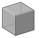
Fillet of solid's edges
To fillet the edges of a solid, use the FilletCalculus3D. This class enables you to calculate fillet on the edges of a Polyhedron3D or a BRep3D. As the resulting solid contains curved faces, the method will always return a BRep.
edges_to_fillet = AllplanUtil.VecSizeTList([1,2,3]) #(1)!

error, fillet_brep = \
    AllplanGeometry.FilletCalculus3D.Calculate(polyhedron,
                                               edges_to_fillet,
                                               radius = 50,
                                               propagation = True)
- By calculating the fillet of a polyhedron edges, we are able to set which edges should be fillet. This parameter has to be provided as VecSizeTList and is required.
Example
The above mentioned implementations are shown in the example Fillet3D located in:
- …\etc\Examples\PythonParts\GeometryExamples\Operations\Others\Fillet3D.pyp
- …\etc\PythonPartsExampleScripts\GeometryExamples\Operations\Others\Fillet3D.py
Fillet of two lines

To calculate a fillet arc between two 2D-lines or 2D-arcs we can use the FilletCalculus2D class. First, we construct the object using the two lines/arcs, which we want to calculate the fillet for, and the fillet radius:
- The FilletCalculus2D object can be constructed using two Line2D or two Arc2D or one arc and one line.
After the object is constructed, we can perform the calculation of the fillet arc(s) using one of the two following methods:
-
GetFillets calculates all the possible fillet arcs. Also the unintuitive ones. Depending on the geometrical relation of the lines/arcs selected for fillet, it may return up to 16 possible solutions!
Tip
Calling the GetFillets method on two lines with a common end will return only one fillet arc. The resulting FilletType is in this case
FT_LL_INTERSECTION_AT_THE_END. -
GetNearest calculates the fillet arc nearest to a given point. Thus, it requires an additional argument in the form of a Point2D:
Info
A very useful method offered by the FilletCalculus2D is GetFilletType. It returns the FilletType object that indicates, what kind of fillet can be calculated with the given lines/arcs.
Example
The implementation of FilletCalculus2D is shown in the example Fillet2D located in:
- …\etc\Examples\PythonParts\GeometryExamples\Operations\Others\Fillet2D.pyp
- …\etc\PythonPartsExampleScripts\GeometryExamples\Operations\Others\Fillet2D.py
Before trying it out, draw two 2D lines or arcs in the model and activate the trace. The example calculates all possible fillet arcs and draws them as preview. The fillet returned by the GetNearest method in relation to the point indicated with the mouse, is highlighted. The example also prints the resulting FilletType in the trace window.
To fillet two coplanar 3D lines, use the FilletCalculus3D. The implementation differs, depending on whether the lines are parallel to each other or not.
Here is how to use the method Calculate on two non-parallel 3D lines:
error, trimmed_first_line, trimmed_second_line, fillet = \
    AllplanGeometry.FilletCalculus3D.Calculate(first_line,
                                               second_line,
                                               radius = 50)
The method will return an error code as a eFilletErrorCode, which tells if the fillet calculation was successful and if not, what was the reason.
To fillet two parallel 3D lines, implement the FilletCalculus as follows
- Note, that there is no fillet radius required, as it will be assumed as the half of the distance between the end of the first and start of the second lins
Warning
This implementation just creates a 3D arc using two points: end point of the first line, and start point of the second line. So, to get expected results, the directions of the lines must be opposite.
Example
The above mentioned implementations are shown in the example Fillet3D located in:
- …\etc\Examples\PythonParts\GeometryExamples\Operations\Others\Fillet3D.pyp
- …\etc\PythonPartsExampleScripts\GeometryExamples\Operations\Others\Fillet3D.py
Intersections
There are four different functions available in the API to either calculate the intersection between two geometries or to just tell, whether they are intersecting. You should choose the right one depending on your goal and type of intersecting geometries. The table should help you: find the type of the first geometry in the first column, and the second geometry in the first row. On the crossing point you will find the function or class suitable for finding the intersection.
| Geometry type | Curve | Plane | Solid |
|---|---|---|---|
| Solid | IntersectRayBRep/Polyhedron | CutBrepWithPlane | Intersect |
| Plane | IntersectionCalculus | Intersect | - |
| Curve | IntersectionCalculus | - | - |
Curve with curve
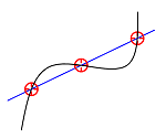
To calculate the point(s) of intersection of two curves, use IntersectionCalculus. This function always returns an intersection point (or several points), therefore it's suitable for calculating intersection between two curves as well as a curve and an areal object, like Plane3D.
intersecting, points = AllplanGeometry.IntersectionCalculus(
    ele1=           first_geometry,
    ele2=           second_geometry,
    eps=            10, #(1)!
    maxSolutions=   3)  #(2)!
- The tolerance is relevant only when calculating intersection with splines
- This parameter is also relevant only when comparing splines. When comparing e.g., polylines (which also may intersect multiple times) all the intersecting points are returned anyway.
Warning
Please note, that IntersectionCalculus does not throw any error, when a wrong type of geometry is passed to it. In this case, just no intersection point is found.
Example
To see, how the function works, run the example IntersectionCalculus located in:
- …\etc\Examples\PythonParts\GeometryExamples\Operations\Intersection\IntersectionCalculus.pyp
- …\etc\PythonPartsExampleScripts\GeometryExamples\Operations\Intersection\IntersectionCalculus.py
Info
Alternatively you can check, whether two curves intersect, without calculation the intersection point. This can be done with the function Intersecting. However, the usage is limited to certain curve types.
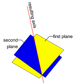
Plane with plane
To calculate the curve resulting from the intersection of two surfaces, like Plane3D or Polygon3D, use Intersect function. Its usage is described in the chapter boolean operations.
Solid with solid
To calculate the solid resulting from the intersection of two solids, use the Intersect function. We describe the usage in the paragraph boolean operations.
Tip
If you just want to check, if two solids intersect, without calculating the boolean intersection, you can use the Intersecting function. To see, how it works, run the example Intersecting located in:
- …\etc\Examples\PythonParts\GeometryExamples\Operations\Intersection\Intersecting.pyp
- …\etc\PythonPartsExampleScripts\GeometryExamples\Operations\Intersection\Intersecting.py
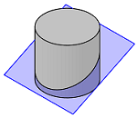
Solid with plane
To find out, if a solid (Polyhedron3D or a BRep3D) is cut by a Plane3D use the function CutPolyhedronWithPlane or CutBrepWithPlane respectively. The usage of both functions is identical.
is_cutting , solid_above, solid_below = \
    AllplanGeometry.CutBrepWithPlane(solid_to_cut, cutting_plane)
Warning
Note, that the solid_above will contain the piece of solid, that is on the positive
side of the plane's normal vector! If this vector points down, the above part
will be below the plane.
Tip
This function will not return the polygon resulting from the intersection, but two solids. To get the polygon, you have to inspect the faces of the solid below and pick the one having the same normal vector, as the cutting plane.
Example
To see, how the function works, run the example CutSolidWithPlane located in:
- …\etc\Examples\PythonParts\GeometryExamples\Operations\Intersection\CutSolidWithPlane.pyp
- …\etc\PythonPartsExampleScripts\GeometryExamples\Operations\Intersection\CutSolidWithPlane.py
Curve with plane
To calculate the intersection point between a curve and a plane, use the IntersectionCalculus described in this chapter
Curve with solid
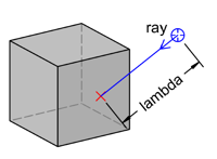
Although there is no function to directly find an intersection point of any type of curve with a solid, the functions IntersectRayPolyhedron and IntersectRayBRep can calculate the intersection of a solid and a ray.
A ray is defined with a Point3D and a direction Vector3D.
error, result = \
    AllplanGeometry.IntersectRayPolyhedron(ray_point,
                                           ray_vector,
                                           polyhedron,
                                           AllplanGeometry.IntersectRayPolyhedronFlag.ePositiveOnly, #(1)!
                                           face_list) #(2)!
- We can set, if the intersection point should be found only in the positive or negative direction of the ray vector, or the one with smallest lambda should be returned. Refer to the documentation of the IntersectRayPolyhedronFlag to see the possible options
- Optionally we can provide a list of face IDs to search intersection on
The result is an IntersectionRayPolyhedron object containing the intersection point as well as other information, like the face number, where the intersection was found, its normal vector and lambda.
- In case an intersection point was found in both positive and negative ray direction, we can set here, which point should preferably be returned. 'False' will return the positive point.
The result is an IntersectionRayBRep object containing the intersection point as well as the face number, where the intersection was found.
Example
the usage of the functions is implemented in the following examples:
- …\etc\Examples\PythonParts\GeometryExamples\BooleanOperations\IntersectRayBRep.pyp
- …\etc\PythonPartsExampleScripts\GeometryExamples\BooleanOperations\IntersectRayBRep.py
- …\etc\Examples\PythonParts\GeometryExamples\BooleanOperations\IntersectRayPolyhedron.pyp
- …\etc\PythonPartsExampleScripts\GeometryExamples\BooleanOperations\IntersectRayPolyhedron.py
Tip
To only check, whether a 3D curve is intersecting a polyhedron or a BRep, you can use the Intersecting function. It is capable of determining whether a solid intersect with a 3D spline or a 3D arc, but without calculating the intersection point. The implementation is shown in the example located in:
- …\etc\Examples\PythonParts\GeometryExamples\Operations\Intersection\Intersecting.pyp
- …\etc\PythonPartsExampleScripts\GeometryExamples\Operations\Intersection\Intersecting.py
Before running the example, draw a solid and a 3D curve (spline or arc) in the model.
Offset
Curve offset
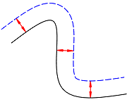
To create a curve parallel to a given one, we can use the Offset function of the geometry module. It is capable of calculating a parallel of following type of curves (2D as well as 3D):
- Arc
- Line
- Polyline
- Spline
- Path
Although this function has many implementations, we can basically divide them into two groups:
- calculation based on source curve and offset distance
- calculation based on source curve and helping point
- This is the most basic implementation of the Offset function for a Line2D.
| Usage tip | Applies to |
|---|---|
| It is possible to calculate several parallel polylines | 3D polyline |
| When calculating parallel to a 3D curve, the function calculates a planar curve in the plane specified in a separate argument as Plane3D | 3D polyline, 3D spline |
| For a 3D line, the offset plane is specified using a special Offset3DPlane object, and NOT by Plane3D! | 3D line |
- This is the most basic implementation of the Offset function for a Line2D, which would calculate a parallel line 100 mm away.
| Usage tip | Applies to |
|---|---|
| It's possible to calculate several parallel polylines | 3D polyline |
| You can ensure, that the segments in the parallel 2D curve have the same orientation as the source curve by providing an additional True/False argument | 2D polyline, 2D spline, 2D path, 3D spline |
| When calculating parallel to a 3D curve, the function calculates a planar curve in the plane specified in a separate argument as Plane3D | 3D polyline, 3D spline |
| For a 3D line, the offset plane is specified using a special Offset3DPlane object, and NOT by Plane3D! | 3D line |
| For a 3D line, apart from distance it is also necessary to specify a point. It will be used only to determine the direction where to calculate the parallel 3d line | 3D line |
Example
All the possible implementations of the Offset function are shown in the example CurveOffset located in:
- …\etc\Examples\PythonParts\GeometryExamples\Operations\Offset\CurveOffset.pyp
- …\etc\PythonPartsExampleScripts\GeometryExamples\Operations\Offset\CurveOffset.py
Before using it, draw some curves (2D or 3D) in the drawing file. After starting the
example, select the input mode (by point or by distance). Even if the offset calculation
was not successful, have a look in the trace, as error_code will always be printed.
Face offset
To create a face offset from a solid, use the class FaceOffset. This class is able to calculate an offset surface or a shell solid out of a given Polyhedron3D or BRep3D.
First, we have to instantiate the FaceOffset object. At this stage we can optionally provide a vector with indices of the faces, we want to calculate offset of. Then, we can call methods on this object to get, what we want.
flowchart LR
    solid[/"Polyhedron
    or
    Brep"/] --> FaceOffset[(FaceOffset)]
    edges[/"Faces to offset
    (optional)"/] --> FaceOffset
    FaceOffset --> is_brep["IsResultBrep()"]
    FaceOffset --> shell["Shell()"]
    FaceOffset --> offset["Offset()"]
    is_brep --> bool[/Is the result brep or polyhedron?/]
    shell --> shell_solid[/Shell solid/]
    offset --> offset_surface[/Offset surface/]
    style edges stroke-dasharray: 5 5
    style FaceOffset stroke:#f00
    style is_brep stroke:#0f0
    style shell stroke:#0f0
    style offset stroke:#0f0
    style solid stroke:#00f
    style shell_solid stroke:#00f
    style offset_surface stroke:#00f
    style edges stroke:#00f
    style bool stroke:#00f
Here is how we can construct the FaceOffset object:
- This argument is optional. If we don't provide it, all faces of the solid will be taken into calculation
Once we have our FaceOffset object constructed, let's focus on the two most important methods of this class: offset and shell
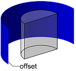
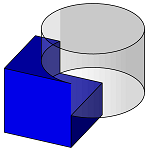
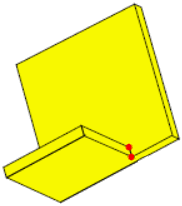
With the Offset method we can calculate offset surfaces to the given face of a solid, as shown on the image to the right. The result will be a geometry without volume, even if the resulting surfaces theoretically enclose a volume.
Abstract
The exception here is the case of calculating offset of all faces of a polyhedron. In this case, the result will be a closed volume Polyhedron3D
error, geo_1, geo_2 = face_offset.Offset(
    offsetDistance      = 100, #(1)!
    direction           = AllplanGeometry.FaceOffset.eNormalDirection, #(2)!
    useOffsetStepPierce = False, #(3)!
    useOrthoVXSplit     = False, #(4)!
    punchDirection      = None) #(5)!
- In case of calculation in both, normal and opposite directions, this will be the distance between the two calculated faces, and not between the source and the resulting faces!
- Here we can set, in which direction to calculate the offset. See the documentation of the eFaceOffsetDirection class to see what options are possible.
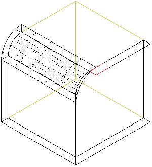
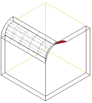
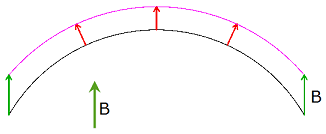
-
Whether to consider the adjoining faces not selected for the calculation. This option will have no effect when all faces are selected (no vector with face indices provided), but also if e.g., all of the faces are orthogonal (cuboid).
Here's an example on the option's impact on the result:
-
When set to True, in some cases the part where source surface turns into the resulting parallel surface will be filled with a solid.
-
Punching direction vector is optional. If not defined (
Noneobject provided), the surfaces will be offset in their normal direction.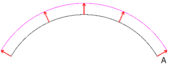
Info
When calculating offset of all faces, providing this vector will not have any impact on the outcome.
Apart from that, when provided, the option
useOffsetStepPierceis ignored.Failure
This vector cannot be coplanar with any of the offset faces, otherwise it will result in an error.
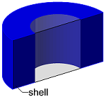
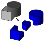
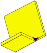
The method Shell will, just as the Offset, calculate the offset surface at a given distance, but it will also fill the space between it and the source face, creating a shell solid. This means, that the resulting geometry will always have a volume. When all faces of a closed solid are taken fot the calculation, the result will be a solid with a hollow core in the shape of the source solid.
error, geo = face_offset.Shell(
    offsetDistance      = 100,
    direction           = AllplanGeometry.FaceOffset.eNormalDirection,
    useOffsetStepPierce = False,
    useOrthoVXSplit     = False,
    punchDirection      = None) #(1)!
- The options of the Shell method are exactly the same, as the Offset so please refer to the previous tab to see the detailed explanation.
Example
The implementation of the FaceOffset class is shown in the example FaceOffset located in:
- …\etc\Examples\PythonParts\GeometryExamples\Operations\Offset\FaceOffset.pyp
- …\etc\PythonPartsExampleScripts\GeometryExamples\Operations\Offset\FaceOffset.py
Quantity take-off
Curves
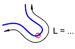
To calculate the length of a curve, use CalcLength function. To get the center of the curve, use a dedicated class CenterCalculus.
Info
In case of an open curve, CenterCalculus calculates the center of the curve, not the curve's center of gravity!
Only for some closed curves, like Polygon3D or a closed BSpline3D the class is capable of calculating the center of gravity of the enclosed area.
Example
The implementation the functions is shown in the examples CalcLength and CenterCalculus, located in:
- …\etc\Examples\PythonParts\GeometryExamples\Operations\QuantityTakeOff\CalcLength.pyp
- …\etc\PythonPartsExampleScripts\GeometryExamples\Operations\QuantityTakeOff\CalcLength.py
- …\etc\Examples\PythonParts\GeometryExamples\Operations\QuantityTakeOff\CenterCalculus.pyp
- …\etc\PythonPartsExampleScripts\GeometryExamples\Operations\QuantityTakeOff\CenterCalculus.py
Area
To calculate the area of a closed and flat geometrical objects, use CalcArea. This function is suitable for planar objects only e.g., Polygon3D. For calculation of curved surfaces, refer to the paragraph below. To calculate the center of gravity of a closed area, use CenterCalculus.
Solids
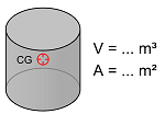
To get quantities from a closed volume solid, use the CalcMass function. It calculates all three key quantities of a solid: volume, surface and the center of gravity. As 3D surfaces are also represented with a BRep3D or a Polyhedron3D, this class is also suitable for calculating the area of a curved surface.
Warning
The function is not capable of calculating the center of gravity of a curved surface. In this case the resulting point will be (0,0,0).
Example
See the CalcMass example to see, how the function works. It is located in:
- …\etc\Examples\PythonParts\GeometryExamples\Operations\QuantityTakeOff\CalcMass.pyp
- …\etc\PythonPartsExampleScripts\GeometryExamples\Operations\QuantityTakeOff\CalcMass.py
Tessellation
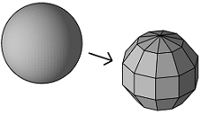
Tessellation is a type of geometry approximation, which involves breaking down the curved surfaces of a BRep into smaller, planar faces (typically triangles or quadrilaterals). This process must be introduced, if we want to convert a BRep3D object into a Polyhedron3D object.
To perform a tessellation in the script we have to introduce two steps:
-
define the parameters of the tessellation in an ApproximationSettings object:
tesselation_settings = AllplanGeometry.ApproximationSettings() tesselation_settings.SetBRepTesselation(density= 0.5, #(1)! maxAngle= AllplanGeometry.Angle(), #(2)! minLength= 0.0, #(3)! maxLength= 0.0)- The density is a factor between 0 and 1, telling how dense the generated mesh of triangles or quadrilaterals should be. The higher the factor, the denser the mesh. This is the only parameter, that is required to be set. Others can be set to zero
- The maximum angle can be set to limit the angle between the resulting polyhedron faces. So, the lower the maximum angle, the smoother the resulting polyhedron. If set to 0 (like shown here) it will get ignored. The value can be set between 1° and 90°
- Setting a minimum and/or maximum length will result in limiting the size of the triangles and quadrilaterals. The higher the minimum length, the sparser the mesh. In opposite, the lower the maximum length, the denser the mesh. Both parameters get ignored, when set to 0.
-
use the settings to create a polyhedron from a BRep using the function CreatePolyhedron:
graph LR
    brep[(BRep3D)] --> tesselation{{"CreatePolyhedron()"}}
    settings[(ApproximationSettings)] --> tesselation
    tesselation --> poly[(Polyhedron3D)]
Example
The full implementation is shown in the example Tessellation located in:
- …\etc\Examples\PythonParts\GeometryExamples\Operations\Others\Tessellation.pyp
- …\etc\PythonPartsExampleScripts\GeometryExamples\Operations\Others\Tessellation.py