Geometry transformation
Geometry transformation is a function that transforms one set of points (which can represent e.g., a geometrical shape) into another set of points in a geometric space. In this chapter we will focus on three types of transformation, which can be performed using the geometry module:
Transformation matrix is an immensely useful object when designing a PythonPart, as it can:
- modify geometry objects; in this context it is referred to as transformation matrix
- be used to place an object (e.g., a PythonPart) in the model space, as it can describe the position and orientation of an object at the same time; in this case it is referred to as placement matrix
- describe the projection in a UVS; in this case in referred to as projection matrix.
Abstract
In the following examples we will be transforming a geometry object in general.
This can be anything: a Line2D as well as
Polyhedron3D.
Assume a 3D geometry, but the logic is the same for 2D objects. The only
difference is that you must use Matrix2D instead of Matrix3D.
Translation
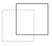
Translation means moving every point of a geometric object in the same direction. The direction is defined by a vector.
In a two-dimensional space, transformation matrix representing a translation by a vector \(\overrightarrow{t} = (t_{x},t_{y})\) looks like this:
In a three-dimensional space, transformation matrix representing a translation by a vector \(\overrightarrow{t} = (t_{x},t_{y},t_{z})\) looks like this:
To construct a matrix like this, we can use following methods:
- SetTranslation - this method makes the matrix describe only one translation.
- Translate - this method adds translation to the matrix.
Example
translation_vector = AllplanGeo.Vector3D(10, 20, 30) #(1)!
transformation_matrix = AllplanGeo.Matrix3D() #(2)!
transformation_matrix.SetTranslation(translation_vector) #(3)!

translated_geometry = geometry_object * transformation_matrix #(4)!
- We define the translation vector first. With this vector we
will move the
geometry_objectby 10 mm in X, 20 mm in Y and 30 mm in Z direction. - We construct an identity matrix first.
-
After setting the translation, the
transformation_matrixlook like this: -
Most of the geometry objects can be multiplied by a transformation matrix from the right side like this. In this case, we become a new, translated object as a result.
Tip
Translation can also be achieved with the Move function. In this case, there is no need to construct a transformation matrix.
Rotation
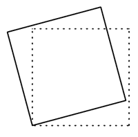
Rotation means moving every point of a geometric object around a defined axis by an angle.
In a two-dimensional space, transformation matrix representing a rotation by an angle \(\theta\) around the origin looks like this:
In a three-dimensional space, transformation matrix representing a rotation by an angle \(\theta\) around the origin looks like this:
To construct a matrix like this, we can use following methods:
- SetRotation - this method makes the matrix describe only one rotation.
- Rotation - this method adds rotation to the matrix.
Example
rotation_axis = AllplanGeo.Line3D(AllplanGeo.Point3D(0, 0, 0),
                                  AllplanGeo.Point3D(0, 0, 1)) #(1)!
rotation_angle = AllplanGeo.Angle.FromDeg(15)
transformation_matrix = AllplanGeo.Matrix3D()
transformation_matrix.SetRotation(rotation_axis,rotation_angle) #(2)!

geometry_object *= transformation_matrix #(3)!
-
The rotation axis is defined using Line. Note, that a Line has start and end point and therefore defined direction. This is important for the rotation direction, which is determined according to the right-hand-rule:

-
Using a dedicated method, we make the matrix describe the rotation only.
- Unlike in the earlier example, here we apply the transformation directly on the
geometry_objectusing in-place multiplication. This is possible for most geometry objects.
Tip
Rotation can also be achieved with the Rotate function. In this case, there is no need to construct a transformation matrix.
Scaling
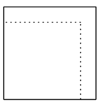
Scaling means enlarging or shrinking a geometry object by a factor. Scaling can be defined by providing scale factors, one for each direction.
Assuming, that \((S_{x},S_{y})\) are the scale factors, the transformation matrix describing scaling would look like this:
Assuming, that \((S_{x},S_{y},S_{z})\) are the scale factors, the transformation matrix describing scaling would look like this:
To construct a transformation matrix describing scaling, we can use following methods:
- SetScaling - this method makes the matrix describe only scaling.
- Scaling - this method adds scaling factors to the matrix.
The reference point for the scaling is in both methods the origin (0,0,0).
Example
transformation_matrix = AllplanGeo.Matrix3D()
transformation_matrix.SetScaling(2,3,4) #(1)!

translated_geometry = AllplanGeo.Transform(geometry_object, transformation_matrix) #(2)!
-
After setting the scaling factors, the
transformation_matrixlook like this: -
Alternatively to multiplication, shown in the examples above, we can use the function Transform to apply the transformation on a geometry object.
Reflection
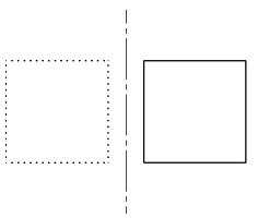
Reflection is a special case of scaling, achieved by scaling with factor -1.
However, the geometry module offers methods to calculate the scaling factors
for reflection transformation, allowing you to define any plane as reference.
The methods are:
- SetReflection - this method makes the matrix describe only reflection.
- Reflection - this method adds reflection to the matrix.
Warning
When mirroring a solid using a transformation matrix, we are generating a negative geometry! This kind of geometry may cause problems later e.g., when creating a section. Therefore, we recommend using the Mirror function.
Projection
A transformation matrix can be constructed as a projection matrix, that can define a view direction. A projection matrix is an ordinary transformation matrix, but it describes a projection, which is why it is called that way. It is particularly useful when we have to define a view direction e.g., when creating a UVS or calculating 2D lines using HiddenCalculus.
We can construct a projection matrix by using the predefined types in the enumeration class eProjectionMatrixType.
Example
We can construct a projection matrix that defines looking on an object from the right side like this:
projection_matrix = AllplanGeo.Matrix3D(AllplanGeo.eProjectionMatrixType.RIGHT_2D)

geometry_object *= projection_matrix #(1)!
- Applying this matrix on a geometry object will simply rotate it in a way, that its right side is visible from above.
Assigning the projection_matrix e.g., to the
ViewMatrix property
of a ViewSectionElement will
create a view from right
Composing transformations
Special methods
As mentioned above, the dedicated methods Rotation, Scaling, Reflection and Translate are adding the corresponding operations, without overwriting the matrix. This allows to construct one matrix that describe multiple operations.
Example
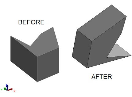
In this example we are constructing a transformation_matrix that
will scale, rotate and translate a geometry object, exactly in this order:
transformation_matrix = AllplanGeo.Matrix3D() #(1)!

# ---- scaling ----
scaling_factors = [1.8, 1.5, 1.2]
transformation_matrix.SetScaling(*scaling_factors) #(2)!

# ---- rotation ----
rotation_axis = AllplanGeo.Line3D(AllplanGeo.Point3D(0, 0, 0),
                                  AllplanGeo.Point3D(1, 1, 1))
rotation_angle = AllplanGeo.Angle.FromDeg(45)
transformation_matrix.Rotation(rotation_axis, rotation_angle) #(3)!

# ---- translation ----
translation_vector = AllplanGeo.Vector3D(10, 20, 30)
transformation_matrix.Translate(translation_vector)  #(4)!

geometry_object *= transformation_matrix  #(5)!
- Create an identity matrix first.
- Setting the scaling first. Note that all three scaling factors are in one list,
but the method needs them separately, therefore the unpacking operator
*. - Adding the rotation around a diagonal axis by 45°.
- Adding the translation.
- Applying the transformation to the object. It will be scaled, rotated and moved.
Matrix multiplication
Using methods mentioned above we can add single operations to an existing transformation matrix. But we can also add a whole set of transformations described in a separate matrix by multiplying them.
Example
Let's assume, that we want to translate a geometry object, and after that
perform all the transformations described in the example above with the
transformation_matrix.
# ---- construct new translation matrix ----
translation_matrix = AllplanGeo.Matrix3D()
translation_vector = AllplanGeo.Vector3D(40, 50, 60)
translation_matrix.SetTranslation(translation_vector) #(1)!

# ---- combine both matrices ----
new_transformation_matrix = translation_matrix * transformation_matrix #(2)!

geometry_object *= transformation_matrix  #(3)!
- The
translation_matrixdescribes a new translation now. - The
new_transformation_matrixwill now combine the translation from the new constructedtranslation_matrixfollowed by all the transformations we defined in the previous example. Note that matrix multiplication is not commutative, meaning the order of multiplication matters! - Applying the transformation to the object. It will be moved, scaled, rotated and moved.