Solids
Object types
In Allplan, two ways are used to describe a solid:
- polyhedron
- boundary representation
Both ways can be used with the Python API and both have their strengths and weaknesses. In this article we will describe the solid creations using both of them.
Polyhedron
A 3D solid defined as polyhedron is defined as a collection of points (vertices). Edges are defined by pointing to start and end vertices. Faces, in turn, are defined by pointing to bounding edges. That means, that the definition is based on points (points -> vertices -> faces). Polyhedron faces are by definition planar.
In Allplan Python API a polyhedron is represented by the Polyhedron3D class.
BRep
A 3D solid defined as brep (boundary representation) is defined as a collection of NURBS surfaces. Every face is bounded with a closed loop, which consists of one or more edges. An edge is a curve, where two surfaces intersect. Each edge is bounded by a vertex at the start and at the end point. Vertices are points, where edges intersect. So, the definition of a brep is based on faces (faces -> edges -> vertices).
In Allplan Python API a brep is represented by the BRep3D class. A NURBS surface is represented by BSplineSurface3D class.
Polyhedron vs. BRep
Allplan's internal graphics kernel is responsible for processing of polyhedrons, whereas the Parasolid engine is responsible for brep processing. For better performance, we recommend using polyhedrons preferably over breps. However, to be absolutely sure what is better in each case, a performance profiling needs to be performed.
Info
When a BRep3D is used to construct ModelElement3D, the element that will be created in Allplan model will be of type BRep3D_Volume_TypeUUID. If, on the other hand, we construct the element using Polyhedron3D, the created object will be of type Volume3D_TypeUUID. When modifying existing object it is important, not to switch between brep and polyhedron.
Basic shapes
Cuboid
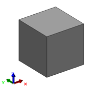
To create a cuboid as brep, we can use the static method CreateCuboid of the BRep3D class.
Example
cuboid = AllplanGeo.BRep3D.CreateCuboid(
    placement=  AllplanGeo.AxisPlacement3D(),
    length=     1000.0,
    width=      2000.0,
    height=     3000.0)
The complete example is available in:
- …\etc\Examples\PythonParts\GeometryExamples\BasicSolids\Cuboid.pyp
- …\etc\PythonPartsExampleScripts\GeometryExamples\BasicSolids\Cuboid.py
Alternatively, we can construct the Cuboid3D object. This object has methods and more properties relevant for a cuboid, like GetLength() or GetGroundPlane(), which might be helpful in further processing.
Example
cuboid = AllplanGeo.Cuboid3D(
    refPoint=   AllplanGeo.Point3D(),
    startPoint= AllplanGeo.Point3D(),
    vec1=       AllplanGeo.Vector3D( 3000,    0,    0),
    vec2=       AllplanGeo.Vector3D(    0, 2000,    0),
    vec3=       AllplanGeo.Vector3D(    0,    0, 1000)) #(1)!
- Note, that all the three direction vectors has to be perpendicular. One way to make sure of that, is to construct an AxisPlacement3D object first and get the vectors from it.
Info
Both, Cuboid3D and BRep3D can be used to construct ModelElement3D.
To create a cuboid as polyhedron, we can use the static method CreateCuboid of the Polyhedron3D class.
Example
cuboid = AllplanGeo.Polyhedron3D.CreateCuboid(
    placement=  AllplanGeo.AxisPlacement3D(),
    length=     1000,
    width=      1000,
    height=     1000
)
The complete example is available in:
- …\etc\Examples\PythonParts\GeometryExamples\BasicSolids\Cuboid.pyp
- …\etc\PythonPartsExampleScripts\GeometryExamples\BasicSolids\Cuboid.py
Warning
When creating a cuboid using the method CreateCuboid, using two points, like this:
make sure point_1 represents the lower left, and point_2 the upper
right point of the cuboid. Otherwise, a negative geometry is created.
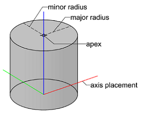
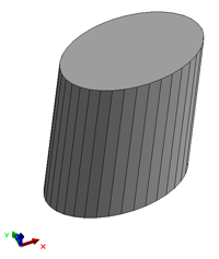
Cylinder
To create a cylinder as brep, we can construct the Cylinder3D object. This object has methods and properties relevant for a cylinder, like GetHeight() or GetZAxis(), which might be helpful in further processing.
Example
cylinder = AllplanGeo.Cylinder3D(
    refPlacement=   AllplanGeo.AxisPlacement3D(),
    radiusMajor=    500,
    radiusMinor=    500,
    apex=           AllplanGeo.Point3D(0, 0, 1000)
)
The complete example is available in:
- …\etc\Examples\PythonParts\ GeometryExamples\BasicSolids\Cylinder.pyp
- …\etc\PythonPartsExampleScripts\ GeometryExamples\BasicSolids\Cylinder.pyp
Failure
An elliptical or oblique Cylinder3D can be used to construct ModelElement3D, without raising any error. However, this will not create any element in the model!
Alternatively, we can use the static method CreateCylinder of the BRep3D class. However, this will result in a BRep3D object, which has less cylinder-specific properties, than the dedicated Cylinder3D class.
To create a cylinder as polyhedron, we must first construct a Cylinder3D and then use the CreatePolyhedron function. This will result in a Polyhedron3D object.
Example
cylinder = AllplanGeo.Cylinder3D(
    refPlacement=   AllplanGeo.AxisPlacement3D(),
    radiusMajor=    500,
    radiusMinor=    300, #(1)!
    apex=           AllplanGeo.Point3D(200, 200, 1000) #(2)!
)

error_code , polyhedron = AllplanGeo.CreatePolyhedron(cylinder, 36) #(3)!
- Because we eventually tessellate the cylinder and create a Polyhedron3D object, we can create an elliptical cylinder here.
- ... for the same reason we can create an oblique cylinder.
- The cylinder will be tessellated into 36 segments. The resulting
polyhedroncan then be used to construct ModelElement3D.
The complete example is available in:
- …\etc\Examples\PythonParts\ GeometryExamples\BasicSolids\Cylinder.pyp
- …\etc\PythonPartsExampleScripts\ GeometryExamples\BasicSolids\Cylinder.pyp
Cone
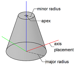
To create a cone as brep, we can construct the Cone3D object. This object has methods and properties relevant for a cone, like GetHeight() or GetZAxis(), which might be helpful in further processing.
Example
cone = AllplanGeo.Cone3D(
    refPlacement= AllplanGeo.AxisPlacement3D(),
    radiusMajor=  500,
    radiusMinor=  200,
    apex=         AllplanGeo.Point3D(0, 0, 1000)) #(1)!

cone_as_brep = AllplanGeo.BRep3D.CreateCone(cone, True) #(2)!
- Make sure, that the apex is on the local Z axis of the cone. Oblique cone will not be created.
- This step is optional. It gives us a BRep3D
as a result. Both
cone(containing a Cone3D) andcone_as_brep(containing a Rep3D object) can be used to construct a ModelElement3D. In this step, however, we can create a cone open at the bottom and top. Basically, the lateral surface only.
The complete example is available in:
- …\etc\Examples\PythonParts\ GeometryExamples\BasicSolids\Cone.pyp
- …\etc\PythonPartsExampleScripts\ GeometryExamples\BasicSolids\Cone.py
To create a cone as polyhedron, we have to create a Cone3D first. Then use it to construct a BRep3D object. This object can be tessellated using the CreatePolyhedron function to become a Polyhedron3D at the end. Refer to this chapter to learn more.
Example
cone = AllplanGeo.Cone3D(
    refPlacement= AllplanGeo.AxisPlacement3D(),
    radiusMajor=  500,
    radiusMinor=  200,
    apex=         AllplanGeo.Point3D(0, 0, 1000))

cone_as_brep = AllplanGeo.BRep3D.CreateCone(cone, True) #(1)!

tesselation_settings = AllplanGeo.ApproximationSettings(AllplanGeo.ASET_BREP_TESSELATION)
tesselation_settings.SetBRepTesselation(0.2, AllplanGeo.Angle(), 0, 0) #(2)!

error_code , cone_as_polyhedron = AllplanGeo.CreatePolyhedron(cone_as_brep, tesselation_settings)
- We cannot tesselate the Cone3D object directly. We have to cast it to BRep3D first.
- Here we can define the tesselation parameters, like density or maximum angle. At least the density have to be defined. Other parameters can be set to zero. See the documentation of the ApproximationSettings class.
The complete example is available in:
- …\etc\Examples\PythonParts\GeometryExamples\BasicSolids\Cone.pyp
- …\etc\PythonPartsExampleScripts\GeometryExamples\BasicSolids\Cone.py
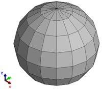
Sphere
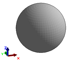
To create a sphere as brep, we can use the method CreateSphere. This will result in a BRep3D object.
To create a sphere as polyhedron, we have to create a BRep first and then tesselate is using the CreatePolyhedron function.
Example
sphere = AllplanGeo.BRep3D.CreateSphere(
    placement=  AllplanGeo.AxisPlacement3D(),
    radius=     500)
tesselation_settings = AllplanGeo.ApproximationSettings(AllplanGeo.ASET_BREP_TESSELATION)
tesselation_settings.SetBRepTesselation(0.2,AllplanGeo.Angle(),0,0) #(1)!
error_code , sphere_as_polyhedron = AllplanGeo.CreatePolyhedron(sphere, tesselation_settings)
- Here we can define the tesselation parameters, like density or maximum angle. At least the density have to be defined. Other parameters can be set to zero. See the documentation of the ApproximationSettings class.
The complete example is available in:
- …\etc\Examples\PythonParts\ GeometryExamples\BasicSolids\Sphere.pyp
- …\etc\PythonPartsExampleScripts\ GeometryExamples\BasicSolids\Sphere.py
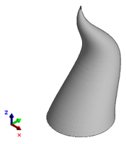
Extrude
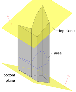
Extrude vertically
The simple operation involving extrusion of a two-dimensional profile in the z-axis direction can be done by creating a ClippedSweptSolid3D. This solid is bounded from the bottom and from the top by arbitrarily oriented planes, represented by Plane3D. The extruded profile is defined by PolygonalArea2D - an object dedicated for constructing ClippedSweptSolid3D, consisting of one or more Polygon2D.
Example
polygon = AllplanGeo.Polygon2D() #(1)!
polygon += AllplanGeo.Point2D()
polygon += AllplanGeo.Point2D(500, 100)
polygon += AllplanGeo.Point2D(800, 800)
polygon += AllplanGeo.Point2D(500, 700)
polygon += AllplanGeo.Point2D(100, 400)
polygon += AllplanGeo.Point2D(0,   900)
polygon += polygon.Points[0]

area = AllplanGeo.PolygonalArea2D() #(2)!
area += polygon #(3)!

top_plane = AllplanGeo.Plane3D(AllplanGeo.Point3D(0,0,1000),
                               AllplanGeo.Vector3D(-0.5,0,1))

bottom_plane = AllplanGeo.Plane3D(AllplanGeo.Point3D(0,0,-1000),
                                  AllplanGeo.Vector3D(0.5,0,1))

swept_solid = AllplanGeo.ClippedSweptSolid3D(area,
                                             bottom_plane,
                                             top_plane) #(4)!

error_code, polyhedron = AllplanGeo.CreatePolyhedron(swept_solid) #(5)!
- We construct a polygon first
- Then we construct a polygonal area
- And append the created polygon to it. We can append more than one.
- The solid is created with the profile, top and bottom bounding planes
- To be able to create a ModelElement3D, a Polyhedron3D must be created.
The complete example is available in:
- …\etc\Examples\PythonParts\GeometryExamples\SolidCreation\ClippedSweptSolid.pyp
- …\etc\PythonPartsExampleScripts\GeometryExamples\SolidCreation\ClippedSweptSolid.py
Extrude along vector
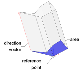
To extrude a plane polygonal profile, oriented freely in the 3D space, along a straight line we can create an ExtrudedAreaSolid3D. The extruded profile is defined by PolygonalArea3D. It is an object dedicated for constructing ExtrudedAreaSolid3D and is defined by one or more Polygon3D. The extrusion direction is defined by a Vector3D, which also can be oriented freely in space. In particular, it does not have to be perpendicular to the extruded polygon.
Warning
All the polygons appended to the PolygonalArea3D have to be coplanar! To check, if the object was constructed successfully, you can e.g., call the GetPlane method and check, if the result is plausible.
Example
polygon = AllplanGeo.Polygon3D()
polygon += AllplanGeo.Point3D()
polygon += AllplanGeo.Point3D(500, 100, 0)
polygon += AllplanGeo.Point3D(800, 800, 0)
polygon += AllplanGeo.Point3D(500, 700, 0)
polygon += AllplanGeo.Point3D(100, 400, 0)
polygon += AllplanGeo.Point3D(0,   900, 0)
polygon += polygon.Points[0]

rotation_matrix = AllplanGeo.Matrix3D()
rotation_matrix.SetRotation(polygon.GetLines()[0],
                            AllplanGeo.Angle.FromDeg(-15))
polygon *= rotation_matrix #(1)!

area = AllplanGeo.PolygonalArea3D()
area += polygon #(2)!

extruded_solid = AllplanGeo.ExtrudedAreaSolid3D() #(4)!
extruded_solid.SetDirection(AllplanGeo.Vector3D(-200,200,1000))
extruded_solid.SetRefPoint(polygon.Points[0]) #(3)!
extruded_solid.SetExtrudedArea(area)

error_code, polyhedron = AllplanGeo.CreatePolyhedron(extruded_solid) #(5)!
- The polygon is plain, but can be rotated freely in the space. In this case, we are rotating the profile by 15° around the first edge of the polygon.
- We append the polygon to the polygonal area. We can append more than one, but all of them must be coplanar.
- In our example, the reference point is set in the first vertex of the profile polygon.
- We construct the object first and set the relevant properties with setter methods.
- To be able to create a ModelElement3D, a Polyhedron3D must be created.
The complete example is available in:
- …\etc\Examples\PythonParts\GeometryExamples\SolidCreation\ExtrudedPolyhedron.pyp
- …\etc\PythonPartsExampleScripts\GeometryExamples\SolidCreation\ExtrudedPolyhedron.py
Sweep
Sweep along path
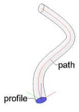
Swept solids are created by sweeping a planar profile along freely defined path. To create such a solid as a BRep we can use any type of path (polyline, spline) and a closed profile (polygon, ellipse, spline). To create a polyhedron in this way, we are limited to polylines only.
The function CreateSweptBRep3D can be used to create a swept brep based on profile and path. Sweeping will be successful when all the following criteria are fulfilled:
- swept profile must be planar
- resulting solid must not intersect himself
- sweeping must not lead to creation of twisted surfaces
Swept profile does not have to be closed. In this case a surface is created.
Example
profile = AllplanGeo.Arc3D( center=  AllplanGeo.Point3D(), #(1)!
                            minor=   100,
                            major=   150,
                            startAngle=  0,
                            deltaAngle=  2 * math.pi)

path_points =  [AllplanGeo.Point3D(),
                AllplanGeo.Point3D(-100,   0,  500),
                AllplanGeo.Point3D(   0,   0,  900),
                AllplanGeo.Point3D(1000,   0, 1300),
                AllplanGeo.Point3D(1000,1000, 1700)]

path = AllplanGeo.Spline3D(path_points) #(2)!

error_code, swept_brep = AllplanGeo.CreateSweptBRep3D(
    profiles_object= [profile], #(3)!
    path_object=      path,
    closecaps=        True, #(4)!
    railrotation=     AllplanGeo.SweepRotationType.Unlocked) #(5)!
- We use ellipse as profile, but any kind of closed profile will be fine. In case profile is not closed, a surface is created
- In this case we use a spline as path, but polyline or b-spline would also be fine
- It is possible to sweep multiple profiles at once. At the end only one solid will be created, even the resulting solids don't touch themselves
- It is possible to create the lateral surface only, without creating a closed volume.
- We can set the rotation of the profile along the sweep path here. When set Unlocked, the angle between the profile and the path will be preserved.
The complete example is available in:
- …\etc\Examples\PythonParts\GeometryExamples\SolidCreation\SweptBRep.pyp
- …\etc\PythonPartsExampleScripts\GeometryExamples\SolidCreation\SweptBRep.py
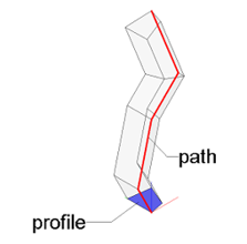
The function CreateSweptPolyhedron can be used to create a swept polyhedron based on polygonal profile and path. Sweeping will be successful when all the following criteria are fulfilled:
- swept profile must be planar
- the profile must be closed as well
- in case of more than one profile: all of them must be coplanar
- resulting solid must not intersect himself
- sweeping must not lead to creation of twisted surfaces
Example
profile_points =   [AllplanGeo.Point3D(),
                    AllplanGeo.Point3D(100, 20, 0),
                    AllplanGeo.Point3D(160,160, 0),
                    AllplanGeo.Point3D(0,  180, 0),
                    AllplanGeo.Point3D(),
                    ]

profile = AllplanGeo.Polyline3D(profile_points)

profiles = AllplanGeo.Polyline3DList()
profiles.append(profile) #(1)!

path_points =  [AllplanGeo.Point3D(),
                AllplanGeo.Point3D(-100,   0,  200),
                AllplanGeo.Point3D(   0,   0,  600),
                AllplanGeo.Point3D( 200,   0,  800),
                AllplanGeo.Point3D( 300, 300, 1000),
                ]

path = AllplanGeo.Polyline3D(path_points) #(2)!

error_code, swept_polyhedron = AllplanGeo.CreateSweptPolyhedron3D(
    profiles=      profiles,
    path=          path,
    closecaps=     True, #(3)!
    railrotation=  True, #(4)!
    rotAxis=       AllplanGeo.Vector3D()) #(5)!
- More than one profile can be swept, but each must be planar and all together must be coplanar
- Path must by a polyline
- It is possible to create the lateral surface only, without creating a closed volume.
- When set to true, a standard profile rotation will be performed, meaning that the angle
between the profile and the path will be preserved. In this case the vector in
rotAxisis ignored. - If the
railrotationwould be set to False, the profile would be rotated around the vector defined here. In this case, we couldn't define a zero vector, as it is now.
Rail sweep
With the function CreateRailSweptBRep3D it is possible to sweep two or more profiles along one or more paths. The same criteria apply to rail sweeping as to sweeping along path:
- swept profiles must be planar
- resulting solid must not intersect himself
- sweeping must not lead to creation of twisted surfaces
Example
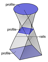
In this example the brep is created by rail sweeping three profiles stored in profiles.
The profiles are a square at the bottom and in the middle(both a Polyline3D)
and a circle on the top (Arc3D). The rails contains
four Spline3D objects, connecting the profiles as shown
on the figure on the right.
error_code, rail_swept_brep = AllplanGeo.CreateRailSweptBRep3D(
    profiles_object= profiles,
    rails_object=    rails,
    closecaps=       True, #(1)!
    uniformScaling=  True, #(2)!
    railrotation=    True) #(3)!
- It is possible to create the lateral surface only, without creating a closed volume.
- When set to true, the profile will be scaled uniformly in all directions to fit into the rails.
- When set to true, the angle between the rail and the profile will be preserved.
The complete example is available in:
- …\etc\Examples\PythonParts\ GeometryExamples\SolidCreation\RailSweptBRep.pyp
- …\etc\PythonPartsExampleScripts\ GeometryExamples\SolidCreation\RailSweptBRep.py
Revolve
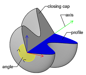
A solid can be created by revolving a profile around an axis. To do that, we can use the function CreateRevolvedBRep3D. The profile is defined as a set of 3D curves e.g., Line3D, Polyline3D or Spline3D. To create a closed volume by revolving, follow these rules:
- the profile curves must compose a closed shape
- resulting profile shapes must be planar
- revolving cannot lead to a solid intersecting himself. This the case e.g., when the axis intersects the profile
Info
As revolving means by definition creating a solid with curved lateral surfaces, the result is always a BRep3D. However, every BRep can be tessellated into Polyhedron3D. Refer to this chapter to learn how.
Example
profile_curves = [] #(1)!

spline = AllplanGeo.Spline3D()

spline += AllplanGeo.Point3D()
spline += AllplanGeo.Point3D(400, 200, 0)
spline += AllplanGeo.Point3D(100, 500, 0)
spline += AllplanGeo.Point3D(500, 700, 0)
spline += AllplanGeo.Point3D(  0, 900, 0)

profile_curves.append(spline)

profile_curves.append(AllplanGeo.Line3D(spline.EndPoint,spline.StartPoint)) #(2)!

axis = AllplanGeo.Axis3D(AllplanGeo.Point3D(),
                         AllplanGeo.Vector3D(0,1,0)) #(3)!

error_code, revolved_brep = AllplanGeo.CreateRevolvedBRep3D(
    profiles_object=    profile_curves,
    axis=               axis,
    rotationAngle=      AllplanGeo.Angle(), #(4)!
    closecaps=          True, #(5)!
    numprofiles=        0) #(6)!
- Profile is defined as a Python list with curves to be revolved. If the curves bound a closed shape, a solid will be created. Otherwise just a surface.
- As the spline is not closed, we append a Line3D connecting its start and end points to the list to have a closed profile.
- The profile will be revolved around the Y axis.
- To perform a full rotation by 360°, we have to set the angle to 0°
- In our case of full rotation, setting this to True will result in a solid. When set to False, only the lateral surface would be created.
- When performing a full rotation, this argument must be set to 0!
The complete example is available in:
- …\etc\Examples\PythonParts\GeometryExamples\SolidCreation\RevolvedBRep.pyp
- …\etc\PythonPartsExampleScripts\GeometryExamples\SolidCreation\RevolvedBRep.py
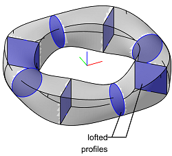
Loft
A solid can be created by joining two or more planar and closed profiles. To do that, we can use the CreateLoftedBRep3D. Lofting will be successful when all the following criteria are fulfilled:
- all profiles must be planar
- the profiles must be closed to create a solid, otherwise surface will be created
- resulting solid must not intersect himself
- lofting must not lead to creation of twisted surfaces
Warning
Unlike in rail sweeping we do not define the rails here. The lofting function will try to connect the first point of the first profile with the first point of the next profile. This may lead to twisted surfaces e.g., when the first profile is a circle (its first point is the one on the X-axis) and the second a square (its first point is the left bottom one).
Example
In this example the brep is created by lofting a set of eight profiles stored in the Python
list profiles. The list consists of four rectangles represented by
Polyline3D objects and four circles represented by
Arc3D. They alternate as shown on the image above.
error_code, lofted_brep = AllplanGeo.CreateLoftedBRep3D(
    outerProfiles_object=     profiles, #(1)!
    innerProfiles_object=     [], #(2)!
    closecaps=                True, #(3)!
    createprofileedges=       False,
    linear=                   False, #(4)!
    periodic=                 True) #(5)!
- The
profilesvariable is a Python list containing closed and planar curves. If the curves are not closed, a surface is created - To create an opening in the lofted profile, we can append its outline to a second Python list.
- To create a closed volume, set this argument to True. Otherwise, only the lateral surface will be created.
- The curves joining the profiles can be created by linear or square interpolation. Set this argument to False, to get a smooth transition between joined profiles.
- When set to True, the first profile will also be the last used for lofting. In our example this will create a closed ring. However, this will lead to a surface being created!
The complete example is available in:
- …\etc\Examples\PythonParts\GeometryExamples\SolidCreation\LoftedBRep.pyp
- …\etc\PythonPartsExampleScripts\GeometryExamples\SolidCreation\LoftedBRep.py
Build from scratch
Using BRep3DBuilder it is possible to build a brep from scratch. It is done in four steps.
The first one is to define the bounding surfaces using the method AddFace. In the most general case, a brep surface is defined as a non-uniform rational b-spline (NURBS). In Allplan Python API, NURBS surfaces are represented with the BSplineSurface3D object. In case of a planar surface, we can also use the much simpler Plane3D object to define a face. When building closed volume brep, the normal vector of a surface is relevant and should point to the outside of the solid.
The second step is to define loops and assign them to surfaces using the method AddLoop. A loop is a closed circuit of edges bounding a face. In a normal case, you will assign one loop to a single face.
The third step is to define the edges and assign them to loops using the method AddEdge. Edges are defined using curves where we expect the surfaces to meet each other. A curve can be of any kind: Arc3D, BSpline3D, Polyline3D or Line3D. When assigning edges to loops, the orientation of the edge is relevant and should follow the right hand rule.
The last step is to define vertices by assigning them to edges using the method AddVertex. Vertices are defined with ordinary Point3D objects. They must be located, where the edges meet each other. To each edge must assign exactly:
- one vertex, if the edge is closed
- two vertices (start and end of an edge, exactly in this order), if the edge is open
All the steps have to be repeated for each face of the brep.
Abstract
The mathematical theory behind NURBS is not straight forward and defining the surface might be challenging. But at the same time it offers basically unlimited possibilities regarding creation of geometrical forms. As this documentation is about the API only, we will not explain the nature of NURBS her. Please refer e.g., to this Wikipedia article to learn more about the basics. You have to know them to understand the following example.
Example
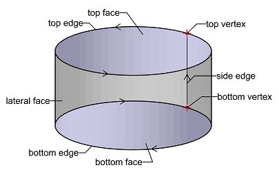
In this example we will construct a cylinder, as shown on the image above, from scratch using brep builder.
In the first step we construct the bottom and the top surfaces. As both are planar, this will be easy:
bottom_surface = AllplanGeo.Plane3D(AllplanGeo.Point3D(),
                                    AllplanGeo.Vector3D(0, 0, 1)) #(1)!

top_surface = AllplanGeo.Plane3D(bottom_surface)
top_surface.Point = AllplanGeo.Point3D(0, 0, 1000) #(2)!
- This surface will bound the cylinder from the bottom. Notice, that the normal vector is pointing upwards - it will be relevant when defining a face
- We copy the bottom surface and change its reference point. The normal vector remains the same: (0, 0, 1)
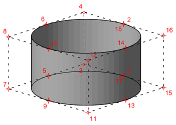
Now we have to define the lateral face of the cylinder as a NURBS surface. In the local U-direction, the surface will be a second degree rational and non-uniform spline with 9 control points. In the V-direction the surface is straight and can be defined with a linear, non-rational uniform b-spline with two control points. In other words: a line.
This means, that the whole surface will have \(9 * 2 = 18\) control points. Their numeration is shown on the image on the right. The points on the surface (1,2,5,6...) will have weights of \(1\) and the ones in the corners (3,4,7,8...) of \(\frac{\sqrt{2}}{2}\). The knots vector for both directions are as follows:
The NURBS surface defined as above is stored in the variable lateral_surface
as a BSplineSurface3D object.
Beside that, the bottom and the top circles are stored in the bottom_edge_curve
and top_edge_curve variables respectively.
Now, as we have all of the components we can start constructing a BRep. We start with initializing the builder and defining the top face with its edges and vertices.
builder = AllplanGeo.BRep3DBuilder()
builder.Init(True) #(1)!


top_face_idx = builder.AddFace(top_surface, sense=  True) #(2)!
top_loop_idx = builder.AddLoop(top_face_idx) #(3)!

top_edge_idx = builder.AddEdge(curve_object=    top_edge_curve, #(4)!
                               curveSense=      True, #(5)!
                               edgeSense=       True,
                               loopIdx=         top_loop_idx, #(6)!
                               precision=       0.5)

top_vertex_idx = builder.AddVertex(point=       top_edge_curve.StartPoint, #(7)!
                                   edgeIdx=     top_edge_idx, #(8)!
                                   precision=   0.5)

builder.CheckLoop(bottom_loop_idx) #(9)!
- Initialize the builder first. We provide
True, because we want to build a closed solid. - The normal vector of the top face of the cylinder has to point to the outside
of the solid. The normal vector of the
top_surfaceis also pointing in that direction, so we provideTruehere. - Assign a loop to the top face.
- An edge has a unique index and is defined by only one curve. In our example,
the
top_edge_curveis a BSpline3D, but an Arc3D would also be fine. -

The normal vector of the top face points to the outside of the solid (upwards) so, according to the right-hand rule, the direction of the loop must be counter-clockwise. The direction of the
top_edge_curveis also counter-clockwise, so we do not have to flip it. Therefore, we set bothcurveSenseas well asedgeSenseto True. -
Here we provide the index of the loop, to which we want to append the edge. The edge is a closed curve (circle), so the loop is now also closed and we don't need to append any more edges to it.
- The top edge is defined with a closed curve (circle), so we need to append only one vertex to it and it will be the starting point of the circle.
- Here we provide the index of the edge, which we want to append the vertex to.
- As we are done with appending the edges to the loop and the vertices to the edges, we can check the loop's topology.
Now we proceed with defining the bottom face.
bottom_face_idx = builder.AddFace(bottom_surface, sense= False) #(1)!
bottom_loop_idx = builder.AddLoop(bottom_face_idx)

bottom_edge_idx = builder.AddEdge(curve_object=     bottom_edge_curve,
                                  curveSense=       False, #(2)!
                                  edgeSense=        True, #(3)!
                                  loopIdx=          bottom_loop_idx,
                                  precision=        0.5) #(4)!

bottom_vertex_idx = builder.AddVertex(point=        bottom_edge_curve.StartPoint,
                                      edgeIdx=      bottom_edge_idx,
                                      precision=    0.5)

builder.CheckLoop(bottom_loop_idx)
- The
bottom_surfacewas defined as Plane3D with its normal vector pointing upwards, but the normal vector of the bottom face must point to the outside of the solid: downwards. Therefore we have to flip the surface direction by setting thesenseto False - The
bottom_edge_curveis a circle with a counter-clockwise orientation. To preserve the right hand rule, we have to flip the curve orientation by setting thecurveSenseto False. Now the bottom edge has a clockwise direction (as shown on the image at the beginning). This is relevant, as we want to use this edge later to define the loop of the lateral surface! - If we would set the
curveSenseto True and theedgeSenseto False, we would create an edge with a counter-clockwise orientation, but would have appended it to the loop in the opposite direction. This would preserve the right hand rule and the topology og the top face loop would be correct. Just when using this edge again in another loop we would have to bear in mind, that its orientation would be counter-clockwise. - If we are not sure, if the surfaces meet exactly in the edges, we can increase the precision. It is advisable to keep the precision as low as possible. the units are mm.
Now we can proceed with defining the lateral face.
lateral_face_idx = builder.AddFace(lateral_surface, sense=  True) #(1)!
lateral_loop_idx = builder.AddLoop(lateral_face_idx)

side_edge_idx = builder.AddEdge(curve_object=    side_edge, #(2)!
                                curveSense=      True, #(3)!
                                edgeSense=       True,
                                loopIdx=         lateral_loop_idx,
                                precision=       0.5)

builder.AddVertex(bottom_vertex_idx, side_edge_idx) #(4)!
builder.AddVertex(top_vertex_idx, side_edge_idx) #(5)!
- The
lateral_surfaceis a BSplineSurface3D object with the normal vector pointing to the outside. No need to flip the sense of it, therefore True. - The variable
side_edgecontains an ordinary Line3D connecting the starting points of the bottom and the top circle. - The
side_edgeis a line going from the bottom to the top. We create an edge with the same direction and append it to the lateral loop as the first element. -
The
side_edgeis defined with an open curve (a line), therefore we need to append two vertices to it: at the start and at the end. Exactly in this order!For the start vertex, we are using an existing one. The one we already defined when creating the bottom face. We refer to it using its index
bottom_vertex_idx. Therefore, we are using the shorter implementation of the AddVertex() function, which requires only 2 arguments. -
As the end vertex, we also use an existing one.
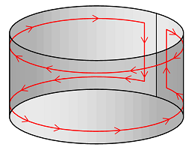
Now, as the side edge is appended to the loop around the lateral surface, we continue adding further edges to close the loop. Keeping in mind, that the loop direction and the normal vector of the face must preserve the right hand rule, the next edge to append would be the top edge (clockwise), then side edge again (but downwards) and the bottom edge (counter-clockwise) as the last one. The schematic course of the lateral face loop is shown in the figure on the right.
builder.AddEdge(top_edge_idx, False, lateral_loop_idx)  #(1)!
builder.AddEdge(side_edge_idx, False, lateral_loop_idx) #(2)!
builder.AddEdge(bottom_edge_idx, False, lateral_loop_idx) #(3)!

builder.CheckLoop(lateral_loop_idx)

brep = builder.Complete() #(4)!
- The orientation of the
top_edgewas set to counter-clockwise, when creating the top face. We have to use it again, but with the opposite orientation, therefore False. Note, that we are appending an already existing edge to the loop. That is why we are using the shorter implementation of the AddEdge() method, requiring three arguments. - Now the side edge, but going downwards. Again, we have to flip its orientation
- And at the end, the bottom edge. The curve's orientation was counter-clockwise, but we flipped it to clockwise, when defining the edge. Now we have to flip it again to counter-clockwise, to close the loop preserving the right-hand rule.
- Now all the loops, edges and vertices are ready, so we are able to build the brep.
The complete example is available in:
- …\etc\Examples\PythonParts\GeometryExamples\SolidCreation\BRepBuilder.pyp
- …\etc\PythonPartsExampleScripts\GeometryExamples\SolidCreation\BRepBuilder.py
It is possible to build a polyhedron from scratch, point-by-point and edge-by-edge and can be done with the Polyhedron3DBuilder class. Building a polyhedron means first defining its vertices. These are ordinary Point3D objects, that are appended to the polyhedron.
In the second step, the edges are defined. These are represented by GeometryEdge objects. Each edge is defined by pointing out two vertices it should connect. The order is relevant here!
In the last step, the faces are defined. These are represented by PolyhedronFace. Each face is defined by pointing out the edges, that should bound the face. The order and the orientation of the edges is here important. Both should be either clockwise or counterclockwise, and that consequently in all faces in the constructed polyhedron!
classDiagram
    direction BT

    class Polyhedron3D{
        GetVertex(index) Point3D
        GetEdge(index) GeometryEdge
        GetFace(index) PolyhedronFace
    }
    class Point3D {
        float X
        float Y
        float Z
    }
    class GeometryEdge{
        int StartIndex
        int EndIndex
    }
    class OrientedEdge{
        int EdgeHandle
        bool Positive
    }
    class PolyhedronFace {
        int Flags
    }
    class Polyhedron3DBuilder{
        AppendVertex(Point3D)
        Complete()
    }

    PolyhedronFace "0..*" --* Polyhedron3D
    GeometryEdge "1..*"   --* Polyhedron3D
    Point3D "2..*"        --* Polyhedron3D
    OrientedEdge "3..*"   --* PolyhedronFace
    Polyhedron3DBuilder   ..> Polyhedron3D        : creates
    Point3D               ..> Polyhedron3DBuilder : requires
Example
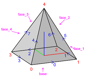
In this example we will construct a pyramid as shown on the image on the right from scratch, using polyhedron builder. In the first step we construct an empty polyhedron and set its type.
- To create solid, we set the type
tVolume. It is also possible to create surfaces or edges only. Refer to the documentation of the class PolyhedronType
In the next step we define the vertices and append them to the pyramid using Polyhedron3DBuilder.
builder = AllplanGeo.Polyhedron3DBuilder(pyramid)

builder.AppendVertex(AllplanGeo.Point3D(-500, -500,    0))
builder.AppendVertex(AllplanGeo.Point3D( 500, -500,    0))
builder.AppendVertex(AllplanGeo.Point3D( 500,  500,    0))
builder.AppendVertex(AllplanGeo.Point3D(-500,  500,    0))
builder.AppendVertex(AllplanGeo.Point3D(   0,    0, 1000))
Now we define the edges by pointing out the vertices using their indexes. The indexes of the vertices are shown on the image above in red.
pyramid.AppendEdge(AllplanGeo.GeometryEdge(0,1)) #(1)!
pyramid.AppendEdge(AllplanGeo.GeometryEdge(1,2))
pyramid.AppendEdge(AllplanGeo.GeometryEdge(2,3))
pyramid.AppendEdge(AllplanGeo.GeometryEdge(3,0))

pyramid.AppendEdge(AllplanGeo.GeometryEdge(0,4))
pyramid.AppendEdge(AllplanGeo.GeometryEdge(1,4))
pyramid.AppendEdge(AllplanGeo.GeometryEdge(2,4))
pyramid.AppendEdge(AllplanGeo.GeometryEdge(3,4)) #(2)!
- Defining the first edge from 0 to 1 will be relevant when constructing the polyhedron faces.
- This is the 8th edge but indexing begins with 0!
In the last step we define the faces by pointing out the edges in the right order and right orientation
base = pyramid.CreateFace(4)
base.AppendEdge(AllplanGeo.OrientedEdge(0, True))
base.AppendEdge(AllplanGeo.OrientedEdge(1, True))
base.AppendEdge(AllplanGeo.OrientedEdge(2, True))
base.AppendEdge(AllplanGeo.OrientedEdge(3, True)) #(1)!

face_1 = pyramid.CreateFace(3)
face_1.AppendEdge(4, True)
face_1.AppendEdge(5, False)
face_1.AppendEdge(0, False)  #(2)!

face_2 = pyramid.CreateFace(3)
face_2.AppendEdge(5, True)
face_2.AppendEdge(6, False)
face_2.AppendEdge(1, False)

face_3 = pyramid.CreateFace(3)
face_3.AppendEdge(6, True)
face_3.AppendEdge(7, False)
face_3.AppendEdge(2, False)

face_4 = pyramid.CreateFace(3)
face_4.AppendEdge(7, True)
face_4.AppendEdge(4, False)
face_4.AppendEdge(3, False)

builder.Complete() #(3)!
- The base of the pyramid is bounded by the edges 0, 1, 2 and 3, meaning clockwise (looking from outside). Because all of the GeometryEdges were also defined this way, the OrientedEdges can be all be constructed in the positive direction.
- The first face is bounded by the edges 4, 5 and 0. They have to be appended in this order to preserve the desired clockwise direction (looking on the face_1 from outside). Also their orientation must align. The edge 4 was defined from vertex 0 to 4, which preserves the clockwise direction. However, the edges 5 and 0 were defined the opposite way.
- At the end we complete the building process. Now the
pyramidis a valid geometry object.
The complete example is available in:
- …\etc\Examples\PythonParts\GeometryExamples\SolidCreation\PolyhedronBuilder.pyp
- …\etc\PythonPartsExampleScripts\GeometryExamples\SolidCreation\PolyhedronBuilder.py