Reinforcement shape definition
In Allplan Python API, a reinforcement shape is represented by the BendingShape object. This object has to be defined in the first place, in order to define a placement.
By choosing the right constructor method, a bending shape can be defined as:
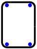
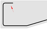
- polygonal shape, to represent rebars arranged transversely to the placement line like e.g., the black stirrup on the image to the right
- point shape, to represent longitudinal bars arranged parallel to the placement line like e.g., the blue corner bars on the image to the right
Info
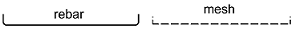
BendingShape can represent a rebar, as well as mesh bending shape, by choosing the right constructor method.
Tip
Constructing the BendingShape using its
built-in __init()__ methods can be challenging, as it requires determining the axis
of the rebar by taking into account its diameter and concrete cover. Therefore,
we recommend using helper classes, listed below, to simplify the definition.
To construct a bending shape, you can choose between following helpers:
- Helper modules of the StdReinfShapeBuilder module (e.g. GeneralReinfShapeBuilder). These modules contains functions for simplified creation of the most common bending shapes. They have limited functionalities, but are easier to implement.
- ReinforcementShapeBuilder class which offers methods to build the bending shape based of any form. Its usage is more complex, but also offers more flexibility.
Model angles
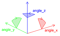
In this article we will be often talking about model angles defined with a RotationUtil object in the context of rotating a shape. This is an object containing three angles describing the rotation of the bending shape around each of the axes: X, Y and Z. These angles and their positive orientation are shown on the image to the right.
Usually, we define bending shapes in a local coordinate system. Since they are mostly flat, usually in the XY plane. However, before placing them, it is necessary to rotate the shape into the correct position.
Example
In the simple example below, the stirrup is defined in a local coordinate system in XY plane (left). It must be placed in a beam in the global YZ plane (right). Therefore, the shape must be rotated around the X axis by +90° and around the Z axis by -90°
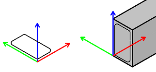
The model angles must be then defined as follows:
Standard shape builder
The standard reinforcement shape builder is a collection of modules, containing helper functions to create a BendingShape. Here is a short overview of the modules and for which use-case they suit best.
| Helper module | Use-case | Example |
|---|---|---|
| GeneralReinfShapeBuilder | For shapes of general usage, like straight bar with hooks or rectangular stirrups | 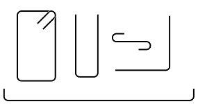 |
| CorbelReinfShapeBuilder | For 3d bended rebar in the column corbel | 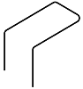 |
| IProfileReinfShapeBuilder | For stirrups in I-section beams |  |
| ProfileReinfShapeBuilder | For stirrups in elements with cross-section in the shape of any polygon | |
| StairsReinfShapeBuilder | For longitudinal bars in a stair flights | |
| DoubleTeeBeamReinfShapeBuilder | For reinforcement of double-T decks |
The UML chart below shows the relationships between relevant classes when using the GeneralReinfShapeBuilder. Follow the graph from bottom to top and construct the objects in your script to get the BendingShape at the end. The GeneralReinfShapeBuilder module is shown on the graph as an example. Nevertheless, other modules from the table above will follow the same principle.
classDiagram
direction BT

class BendingShape{
    int Diameter
    int steelGrade
    BendingShapeType bendingShapeType
    float hookLengthStart
    float hookAngleStart
    HookType hookTypeStart
    float hookLengthEnd
    float hookAngleEnd
    HookType hookTypeEnd
    VecDoubleList BendingRoller
    Polyline3D ShapePolyline
}

class GeneralReinfShapeBuilder{
    <<Module>>
    create_longitudinal_shape_with_hooks()
    create_l_shape_with_hooks()
    create_stirrup()
    create_u_link()
}

class ReinforcementShapeProperties{
    float diameter
    float bending_roller
    int steel_grade
    int concrete_grade
    BendingShapeType bending_shape_type

    rebar()
}

class ConcreteCoverProperties{
    float left
    float right
    float top
    float bottom
}

class RotationUtil{
    float angle_x
    float angle_y
    float angle_z
}

class BendingShapeType{
    <<Enumeration>>
    ColumnStirrup
    LongitudinalBar
    OpenStirrup
    Stirrup
    ...
}

GeneralReinfShapeBuilder --> BendingShape : creates
ConcreteCoverProperties --> GeneralReinfShapeBuilder : requires
RotationUtil --> GeneralReinfShapeBuilder : requires
ReinforcementShapeProperties --> GeneralReinfShapeBuilder : requires
BendingShapeType "1" --o ReinforcementShapeProperties
Example
Let's construct a stirrup shape as shown on the image to the right. According to the graph above, first we need the BendingShapeType:
Now we can define the ReinforcementShapeProperties
shape_properties = ReinforcementShapeProperties.rebar(
    diameter           = 8, #(1)!
    bending_roller     = 4, #(2)!
    steel_grade        = -1, #(3)!
    concrete_grade     = -1, #(4)!
    bending_shape_type = bending_shape_type)
- The stirrup will be 8 mm in diameter
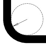
- The bending roller diameter is defined as 4 * rebar diameter for all bending points.
- We use the steel grade from the current Allplan settings
- We use the concrete grade from the current Allplan settings
The next element is the ConcreteCoverProperties:
- We weep it simple and define all the covers as 25 mm. We could also use shorter
notation:
ConcreteCoverProperties.all(25)
Now we have all objects required to define the shape:
shape = GeneralReinfShapeBuilder.create_stirrup(
    length               = 300, #(1)!
    width                = 500,
    model_angles         = RotationUtil(0, 0, 0), #(2)!
    shape_props          = shape_properties,
    concrete_cover_props = concrete_covers,
    stirrup_type         = AllplanReinforcement.Column, #(3)!
    hook_length          = 0)   #(4)!
- This is the x-dimension of the concrete cross-section. Not the length of the stirrup itself! Concrete covers will be subtracted.
- For the purposes of this example, we set all the angles to 0°. This will create the stirrup shape in the XY plane. Refer to this paragraph to learn how to rotate the shape for your use-case.
- This argument is optional. We want the hooks to be bend with 135°, that is why we define it. If it would be skipped, the hooks will be 90°.
- This argument is optional.
0is the default value and means that the hook's length will be calculated automatically based on the current norm.
The created shape can be then used to create placement. Refer to this article
to learn, how to do it.
To see, what kind of other shapes are possible with GeneralReinfShapeBuilder refer to the example GeneralShapeBuilder. It shows the implementation of all functions offered by the module and is located in:
- ...\Etc\Examples\PythonParts\ReinforcementExamples\BarShapes\GeneralShapeBuilder.pyp
- ...\Etc\PythonPartsExampleScripts\ReinforcementExamples\BarShapes\GeneralShapeBuilder.py
Tip
The bending roller can, depending on the national standards, depend on multiple factors like rebar diameter, steel grade, etc. Allplan Python API already offers the BendingRollerService class that can calculate the bending roller based on the currently selected norm. It takes all relevant factors into account.
Reinforcement shape builder
The bending shape can be also created using the helper class ReinforcementShapeBuilder. Use this class especially, when your bending shape is unusual and cannot be created using modules of the StdReinfShapeBuilder.
The UML chart below shows the relationships between the relevant classes when using the ReinforcementShapeBuilder. Follow it from bottom to top and construct the objects in your script to get the BendingShape at the end.
Note
The two data structures, that describes the geometry of a shape:
Can be used alternatively. Decide, which one is more convenient to use in your case and stick to it.
classDiagram
direction BT

class BendingShape{
    int Diameter
    int steelGrade
    BendingShapeType bendingShapeType
    float hookLengthStart
    float hookAngleStart
    HookType hookTypeStart
    float hookLengthEnd
    float hookAngleEnd
    HookType hookTypeEnd
    VecDoubleList BendingRoller
    Polyline3D ShapePolyline

    rotate(RotationUtil)
}

class RotationUtil{
    float angle_x
    float angle_y
    float angle_z
}

class ReinforcementShapeBuilder {
    AddSides(BarShapeSideDataList)
    AddPoints(BarShapePointDataList)
    SetHookStart(length,angle,HookType)
    SetHookEnd(length,angle,HookType)
    CreateShape(ShapeProps)
    CreateStirrup(ShapeProps,StirrupType)
}

class ReinforcementShapeProperties{
    float diameter
    float bending_roller
    int steel_grade
    int concrete_grade
    BendingShapeType bending_shape_type

    rebar()
}

class BarShapeSideDataList{
    <<DataClass>>
}

class BarShapePointDataList{
    <<DataClass>>
}

class BendingShapeType{
    <<Enumeration>>
    ColumnStirrup
    LongitudinalBar
    OpenStirrup
    Stirrup
    ...
}

class HookType{
    <<Enumeration>>
    eAnchorage
    eAngle
    eStirrup
}

class StirrupType{
    <<Enumeration>>
    Normal
    Column
    Torsion
    ...
}

RotationUtil <.. BendingShape : uses
ReinforcementShapeBuilder ..> BendingShape : creates
ReinforcementShapeProperties --> ReinforcementShapeBuilder : requires
BarShapeSideDataList "*" --o ReinforcementShapeBuilder
BarShapePointDataList "*" --o ReinforcementShapeBuilder
HookType ..> ReinforcementShapeBuilder
StirrupType ..> ReinforcementShapeBuilder
BendingShapeType --> ReinforcementShapeProperties : requires
Free form rebar
Before creating a rebar shape using ReinforcementShapeBuilder the geometry of the shape must be defined using one of the following objects:
Abstract
This paragraph is about two-dimensional bar shapes. Therefore, whenever we are talking about points or lines, we mean the Point2D or Line2D respectively. To learn about 3D reinforcement shapes, scroll down to this paragraph
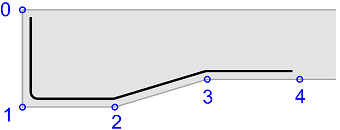
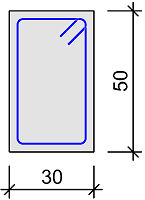
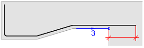
Using BarShapePointDataList, we can define the rebar shape by defining the vertices of the concrete cross-section polygon. To define a shape like the one shown on the right, we have to define a list with 7 elements in total: 5 points and 2 concrete covers:
shape_data = BarShapePointDataList([30, #(1)!
                                    (pnt_0, 30),
                                    (pnt_1, 30),   #(2)!
                                    (pnt_2, 30, 4),#(3)!
                                    (pnt_3, 30),
                                    (pnt_4, 30),
                                    30])
-
The first element of the list should be the concrete cover at the start of a rebar. If we skip it, it will be set to 0.
-
Further elements are two-elements tuples with the first element being the vertex of the shape's reference polyline, and the second the concrete cover.
- We can optionally provide third element to the tuple being the bending roller factor.
Having the list with points, we can now append it to the shape:
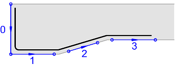
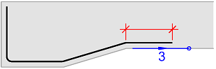
Using BarShapeSideDataList we can define the rebar shape by defining the vertices of the concrete cross-section polygon. To define a shape like the one shown on the right, we have to define a list with 6 elements in total: 4 sides and 2 concrete covers:
shape_data = BarShapeSideDataList([30, #(1)!
                                   (line_0, 30), #(2)!
                                   (line_1_start,line_1_end, 30), #(3)!
                                   (line_2, 30, 4), #(4)!
                                   (line_3, 30),
                                    30]) #(5)!
-
The first element of the list should be the concrete cover at the start of a rebar. If we skip it, it will be set to 0.
-
Further elements are two-element tuples with the first element being the side (Line2D) of the shape's reference polyline, and the second the concrete cover to this side.
- Alternatively, instead of Line2D we can provide the side's start and end point as Point2D.
- Optionally, we can provide third element to the tuple being the bending roller factor.
-
The last element is the concrete cover at the end. Just as the cover at start, we can skip it.
Note
Note, that in the given example, the end point of the first line and the start point of the second one do not have to coincide. This is because they don't have to. The created shape will still be a continuous rebar.
Having the list with sides, we can now append it to the shape:
Hook
To add a hook at the beginning and/or end of the rebar shape, we can use the methods SetHookStart or SetHookEnd.
Note
Hook in Allplan is treated like a special rebar leg. It can be modified only with dedicated menu functions.
shape_builder.SetHookStart(length = 0,  #(1)!
                           angle  = 90,
                           type   = AllplanReinforcement.HookType.Anchorage)  #(2)!
- Setting the length to 0 will calculate the hook's length based on the norm selected in the Allplan settings
- Setting the right HookType is particularly relevant, when the hook's length should be calculated automatically, as different rules may apply for e.g., anchorage hooks and hooks in column stirrups.
Anchorage
To anchor the bar beyond the last and/or first shape point, use the SetAnchorageEnd or SetAnchorageStart method. This methods will extend the last or first segment of the rebar beyond by the specified length, ensuring its anchorage.
Tip
The calculation of the anchorage length will not be done automatically by setting
the length to 0, as it is the case with hooks. However, you can use the
AnchorageLengthService
helper class to determine the length based on the current norm and relevant
parameters, such as concrete grade or \(\frac{A_{s,req}}{A_{s,prov}}\) factor
Set length of leg
Using the SetSideLengthStart or SetSideLengthEnd methods will change the length of the first or last leg of the rebar to the pre-defined one. This might be particularly useful, if the first or last leg of the rebar is used solely for anchorage. The last or first point of the bending shape will then only determine the direction of the leg.
After defining the shape points or sides, hooks, anchorage, etc. we are ready to create the shape:
shape_propertiesis the ReinforcementShapeProperties object. We created it in the example in the chapter above.
Example
To try out the possibilities of the ReinforcementShapeBuilder shown in this article, run the example FreeFormReinforcementShapeBuilder located in:
- ...\etc\Examples\PythonParts\ReinforcementExamples\BarShapes\FreeFormReinforcementShapeBuilder.pyp
- ...\etc\PythonPartsExampleScripts\ReinforcementExamples\BarShapes\FreeFormReinforcementShapeBuilder.py
Closed stirrup
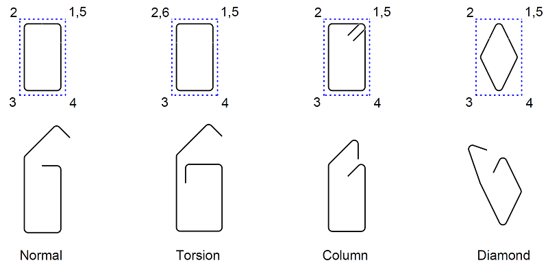
To create a closed stirrup, we can use the method CreateStirrup provided by the ReinforcementShapeBuilder. It requires an additional parameter of StirrupType that defines, how the points are going to be interpreted. In the overview below shows, what kind of stirrup can be achieved with each type.
Example
Let's construct a closed stirrup, as shown on the image to the right, using the ReinforcementShapeBuilder. First, we need to define the ReinforcementShapeProperties:
shape_properties = ReinforcementShapeProperties.rebar(
    diameter           = 8,
    bending_roller     = 4,
    steel_grade        = -1,
    concrete_grade     = -1,
    bending_shape_type = AllplanReinforcement.BendingShapeType.Stirrup) #(1)!
- This argument does not influence the geometry of the shape, but carries the information for Allplan, how to draw the rebar scheme in the bending schedule! See possible options in the API reference
In this example we will define the shape using the BarShapePointDataList object.
which will consist of pairs: point and concrete cover, that should apply to the leg between the given point and the previous one. The list will look like this:
shape_data = BarShapePointDataList(
    [(AllplanGeo.Point2D(300, 500),  0), #(1)!
     (AllplanGeo.Point2D(  0, 500), 25),
     (AllplanGeo.Point2D(  0,   0), 25),
     (AllplanGeo.Point2D(300,   0), 25), #(2)!
     (AllplanGeo.Point2D(300, 500), 25), #(3)!
     ])
- We begin with the shape definition there, where the stirrup hooks should be located: in the top right corner. The concrete cover for the first point is irrelevant, as there is no previous point to refer to, so we can provide any value.
- Any point can be also defined with extra value overwriting the bending roller factor,
like this:
(AllplanGeo.Point2D(300, 0), 25, 10). This would result in this particular leg being bent with a bending roller diameter of 10 * rebar diameter, instead of the standard value of 4, defined in theshape_properties. -
If the concrete cover is positive, we have to define the points anticlockwise to get the shape inside the polygon.
To create a closed stirrup, the last point do not have to be equal to the first one! Relevant here is the number of points:
- less than 3 will not create a valid shape
- 3 points will create an open stirrup
- 4 or more will create a closed stirrup
To have the hooks bent in 135°, we have to define the stirrup type as
AllplanReinforcement.StirrupType.Column. Knowing that, we are ready to create
the bending shape:
shape_builder = AllplanReinforcement.ReinforcementShapeBuilder() #(1)!

shape_builder.AddPoints(shape_data) #(2)!

shape = shape_builder.CreateStirrup(shape_properties, #(3)!
                                    AllplanReinforcement.StirrupType.Column)
- The ReinforcementShapeBuilder helper class needs to be instantiated first
- We append the shape points defined as BarShapePointDataList using the AddPoints method.
- At the end, we create the stirrup shape using the CreateStirrup method
To see the full implementation, refer to the example StirrupReinforcementShapeBuilder located in:
- ...\etc\Examples\PythonParts\ReinforcementExamples\BarShapes\StirrupReinforcementShapeBuilder.pyp
- ...\etc\PythonPartsExampleScripts\ReinforcementExamples\BarShapes\StirrupReinforcementShapeBuilder.py
3D bar shape
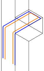
The definition of a 3D rebar shape, like shown on the image to the left, can be done in two ways:
- By providing 2D points (in BarShapePointDataList) or 2D lines (in BarShapeSideDataList) and an additional parameter representing the local z-coordinate.
- By providing 3D points or 3D lines
Abstract
In in the code snippets below we will use the BarShapeSideDataList data class. However, the same principles can be applied when using the BarShapePointDataList
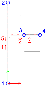
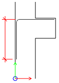
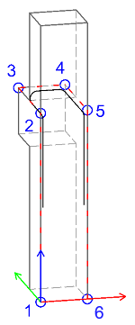
To construct a 3D shape using 2D points we have to assume some local coordinate system. In our example, its origin is at the bottom of the column, and the local Y-axis goes upwards along the column's axis.
We will define the sides by their start and end points. You can see them marked blue on the image on the left. The corbel rebar has 5 legs, so we need to define 5 sides. They are represented with red dashed lines and numbers with the orientation.
shape_data = BarShapeSideDataList(
    [(pnt1, pnt2, -cover, bending_roller),
     (pnt3, pnt4, -cover, bending_roller),
     (pnt4, pnt4,  cover + diameter, bending_roller, z_coord), #(1)!
     (pnt4, pnt3,  cover, bending_roller, z_coord),
     (pnt2, pnt1,  cover, bending_roller, z_coord),
     ])
- You can't see the third side on the image, because it goes downwards along the local Z-axis,
as the
z_coordis defined as-thickness + 2 * cover, so it's negative.
With the geometrical shape data defined like this, we can construct the shape:
shape_builder = AllplanReinf.ReinforcementShapeBuilder()
shape_builder.AddSides(shape_data)
shape_builder.SetSideLengthStart(side_length) #(1)!
shape_builder.SetSideLengthEnd(side_length)
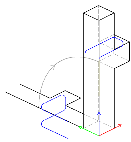
shape = shape_builder.CreateShape(shape_props)
shape.Rotate(RotationUtil(90, 0, 0), AllplanGeo.Point3D()) #(2)!
-
Here we are setting the length of the first and last leg.
-
We created the shape in a local coordinate system, where the Y-axis were parallel to the column's height. In the global system, the Z-axis is parallel to the column. We have to rotate the shape by 90° around the X-axis
Tip
Instead of transforming the generated shape from the local to global coordinate
system with shape.Rotate(...) method, we could have instantiated the
ReinforcementBuilder
with a transformation matrix, like this:
trans_mat = RotationUtil(-90, 0, 0).get_rotation_matrix()
shape_builder = AllplanReinf.ReinforcementShapeBuilder(trans_mat)
Note, that in this case the trans_mat should describe the opposite: transformation
from global to local coordinate system! You can learn, how to construct a
transformation matrix in this article
We can construct a 3D rebar shape using 3D points. In this case, the point coordinates will be given in the global coordinate system. Here is how we define the five legs of the 3D rebar using points as shown on the image to the left:
shape_data = BarShapeSideDataList(
    [(pnt1, pnt2, cover, bending_roller),
     (pnt2, pnt3, cover, bending_roller),
     (pnt3, pnt4, cover, bending_roller),
     (pnt4, pnt5, cover, bending_roller),
     (pnt5, pnt6, cover, bending_roller),
    ])
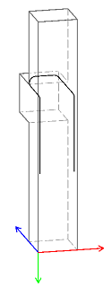
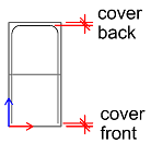
However, for the definition of the concrete covers, we have to assume a local coordinate system.
The XY plane of this coordinate system will be used as offset plane for the concrete_cover
defined above in the shape_data. In addition to that, we will define two concrete covers: at the
front and at the back. These are the covers in the local Z-direction. In our case,
the local Z axis will be the same as the global Y axis, as shown on the image to the right.
Knowing that, we can construct the ReinforcementShapeBuilder like this:
trans_mat = RotationUtil(90, 0, 0).get_rotation_matrix() #(1)!

shape_builder = AllplanReinf.ReinforcementShapeBuilder(
    shapePlaneMatrix = trans_mat,
    create3DShape    = True,
    localZCoverFront = cover, #(2)!
    localZCoverBack  = cover + diameter)

shape_builder.AddSides(shape_data)
shape_builder.SetSideLengthStart(side_length) #(3)!
shape_builder.SetSideLengthEnd(side_length)

shape = shape_builder.CreateShape(shape_props)
- The
trans_matdescribes the transformation from local to global coordinate system with a rotation by 90° around the global X axis. -
The concrete covers at the front and at the back are measured along the local Z axis. Here is a view from the top:
-
Here we are setting the length of the first and last leg.
Example
Both implementations explained above are shown in the example CorbelBar3D located in:
- ...\etc\Examples\PythonParts\ReinforcementExamples\BarShapes\CorbelBar3D.pyp
- ...\etc\PythonPartsExampleScripts\ReinforcementExamples\BarShapes\CorbelBar3D.py
Point shape
A BendingShape can be defined as point shape. This type of shape is particularly useful in combination with certain types of placements, such as extrusion or sweeping, in order to create longitudinal bars. Such bending shape is constructed using a Point3D and a diameter, like this: