Connections
Thanks to connections, a PythonPart element can interact with other, native ALLPLAN elements or react to changes done on them. There are several types of connections resulting in different behavior.
-
Association
A PythonPart element can be associated with another element (also another PythonPart) so that any modification of this element triggers the update of the connected PythonPart.
-
Docking points
Docking points in a PythonPart element allows the user to connect other native elements, such as associative dimension lines, with these points. After modification of the PythonPart, these elements gets updated
-
Plane connection
A PythonPart element can be connected with planes defined in the ALLPLAN Floor Manager. This will result in the PythonPart being updated whenever the user changes the planes in the Floor Manager
Association

Association is a directional relationship. This means, that there is always a source element (aka parent) and a target element (aka child).
Modification of the source triggers the update of the target
flowchart LR
    Source["`**Source**
    any element`"]

    Target["`**Target**
     PythonPart`"]

    Source-->|association| Target
    style Source stroke:#0000CC
    style Target stroke:#CC0000
Because an update can be performed only on a PythonPart and not on a native ALLPLAN element (such as wall or 3D object), the PythonPart will always be the target.
Warning
Under the hood, during the update the framework simulates reactivation of the PythonPart and terminating it directly after, just like the user would double-click on PythonPart and then immediately hit Esc. The palette and handles are suppressed during this process.
Associate with any element
Here are the steps you need to follow, to create a one-directional association between your PythonPart (target) and other element (source) of any kind.
Step 1: Define hidden parameters
In the third step, you will have to save the UUID of the source element in a parameter. Therefore, define beforehand a string parameter in the PYP-file in the hidden page:
<Parameter>
    <Name>SourceElementUUID</Name>
    <Value></Value>
    <ValueType>String</ValueType>
</Parameter>
Why?
Why do I need to save this UUID as a parameter?
You need to save the UUID of the source element, you don't want the user to select it every time he reactivates the PythonPart for modification. Once created, PythonPart has to remember it.
Also in the third step, you will have to save the timestamp of the source element. Define an integer parameter for it e.g., like:
<Parameter>
    <Name>SourceElementTimeStamp</Name>
    <Value></Value>
    <ValueType>Integer</ValueType>
</Parameter>
Why?
Why do I need to save the time stamp of the source element?
ALLPLAN checks, whether a PythonPart was changed, based on a hash value generated from all parameter values. If all PythonPart parameters stays the same, hash also remains the same and ALLPLAN does not apply any changes to the PythonPart.
Imagine following scenario: The user has placed the PythonPart and associated it with an element. Now he modified the element, which triggers the PythonPart update. But because none of the PythonPart parameter values gets changed, the results are not applied. If you save the timestamp of the source element (or any other property, whose change should result in PythonPart being changed) as a parameter, it will always be different. Hence, the update will always be applied.
You don't have to rely on timestamp. If your PythonPart is associated with a wall and should be updated only, when e.g., the wall's height changes, save the height rather than the timestamp.
In the last step, you will have to provide the name of a parameter with the UUID of the target element (your PythonPart). Define it similarly, as string e.g., like:
Why?
Why do I need to save the UUID of my PythonPart as parameter?
For the case, when the user copies the PythonPart and then tries to modify the copy. You might want to handle this case in a special way, e.g. like this:
Step 2: Get the base element adapter of the source element
In the creation mode, you probably want the user to select the source element, so you need to introduce an element selection. If you are creating your PythonPart as a script object, refer to this article to learn, how to do it. If you are creating an interactor, refer to this article.
Whatever your case is, let's assume for further considerations, that the element adapter is
saved under self.source_element
You don't want the user to select the source element every time he reactivates the PythonPart. You should therefore obtain the BaseElementAdapter based on the UUID, you will have saved as a parameter in the third step.
if self.is_modification_mode: #(3)!
    source_element_guid = AllplanEleAdapter.GUID.FromString(self.build_ele.SourceElementUUID.value) #(1)!
    self.source_element = AllplanEleAdapter.BaseElementAdapter.FromGUID(source_element_guid, self.doc)  #(2)!
- First, construct a GUID object from string.
- Then construct a BaseElementAdapter from a GUID. Bare in mind, that this statement will return an Null element adapter, if the source element was deleted or moved to another DF.
-
This if statement is valid for a script object. In an interactor use:
Step 3: Save the UUID and the timestamp
Once you have the BaseElementAdapter of the source element, obtain its UUID and timestamp by calling the GetModelElementUUID and GetTimeStamp respectively and save both in the hidden parameters defined the first step:
self.build_ele.SourceElementUUID.value = str(self.source_element.GetModelElementUUID())
self.build_ele.SourceElementTimeStamp.value = str(self.source_element.GetTimeStamp())
Step 4: Create PythonPart
Now introduce the business logic and calculate the geometry of your PythonPart. You can use any data from the source element e.g., its geometry:
Step 5: Associate the Python Part with the source element
Construct a ConnectToElements object and save the UUID of the source element in it:
- Note, that you provide a list here. It is possible to associate the PythonPart with multiple elements. In this case, modification of any of these elements would. trigger the modification of the PythonPart
In a script object PythonPart, when constructing the
CreateElementResult in the
execute() method, provide additional data fields
connect_to_ele and uuid_parameter_name, like:
def execute(self) -> CreateElementResult:
    ...
    return CreateElementResult(elements, handles,
                               connect_to_ele      = connect_to_elements,
                               uuid_parameter_name = "PythonPartUUID") #(1)!
- Provide the name of the hidden parameter from the first step here - PythonPart framework will take care of saving the UUID of the PythonPart in it
In an interactor PythonPart, do not use the CreateElements function to create the elements. Instead, use the PythonPartTransaction (also described in this article). Here is an example:
pyp_transaction = PythonPartTransaction(self.document,
                                        connect_to_ele = connect_to_elements) #(1)!
...
pyp_transaction.execute(placement_matrix,
                        coord_input.GetViewWorldProjection(),
                        model_element_list,
                        self.modification_ele_list,
                        uuid_parameter_name = "PythonPartUUID") #(2)!
- Here is where you provide the ConnectToElements object
- Here comes the name of the parameter from the 1st step. PythonPart framework will take care of saving the UUID of the PythonPart in it.
Tip
Steps 1-3 can be implemented in the __init__() method of your script object or interactor.
Step 4 is up to you - it is your business logic. Step 5 should be implemented in the
execute() method in case of script object or,
in case of an interactor, wherever the element creation is implemented (presumably in
the on_cancel_function)
Troubleshooting
Connecting a PythonPart to another element may cause problems in certain situations, so it is crucial to consider them beforehand, during the design of a PythonPart. Pay attention to the following:
-
Prepare your PythonPart for being updated
Make sure that reactivating your PythonPart with double-click and hitting Esc directly after that leads to clean termination. If that is not the case, ALLPLAN will get stuck during the update.
-
Test all modification scenarios
Most of the time, there is more than one way how a native ALLPLAN element can be modified. For example, a wall can be modified by: handles, using stretching entities function, changing plane references, using join components function, etc. Test your PythonPart by reproducing all possible modification scenarios and check, if the PythonPart update is done correctly.
-
Test undo function
After each modification of the source element, try to undo the changes and check, if both the modification of the source element, as well as the connected PythonPart is undone successfully
-
Prepare your PythonPart for the source element being deleted or moved to another DF
ALLPLAN does not handle these cases automatically. Your PythonPart will remain undeleted, but after reactivating it, the element adapter in the see step 2 will be a null object.
If you notice any unexpected behavior of ALLPLAN, please report the problem.
Example on GitHub
The complete implementation is shown in the example PythonPartElementConnection ( PYP | PY).
Docking points
The docking points of a PythonPart can be used to connect other ALLPLAN elements with these points. A good example are the associative dimension lines.
Depending on the dynamic state of the PythonPart elements, the docking points are created differently.
Static PythonPart
In a PythonPart, in which:
- the geometry element count and order are static AND
- the point count and order inside the geometry elements is static
the docking points are generated automatically from the geometry elements of the PythonPart without further action needed.
Dynamic element count
In a PythonPart, in which:
- the geometry element count and order are dynamic AND
- the point count and order inside the geometry elements is static
The docking points must be made unique. To do it, a docking point key must be assigned to each model element of the PythonPart. This must be implemented in the script using the SetDockingPointsKey method:
polyhedron_element = AllplanBasisEle.ModelElement3D(com_prop, polyhed)

polyhedron_element.SetDockingPointsKey("Polyhed")
The docking point keys should be assigned in a way that the elements, whose points can be used for meaningful dimension lines, always become the same key.
Example
In the following example, a PythonPart is created with a dynamic count of polyhedrons.
The docking point keys are created from the left and right side, meaning that the
far-left and far-right polyhedrons always become the same docking point key,
the L0 and R0 respectively. The objects next to them become the keys
L1 and R1 respectively and so one...
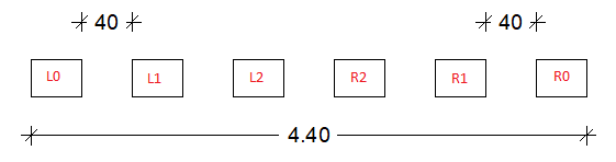
This results in last polyhedrons having the same docking point key, regardless of the total number of the polyhedrons. This makes it possible to place an associative dimension line from the far-left to the far-right polyhedron, which will remain after changing the count of polyhedrons:
Dynamic PythonPart
In a PythonPart, in which:
- the geometry element count and order are dynamic AND
- the point count and order inside the geometry elements is dynamic
The function create_docking_points must be implemented in the script. This function must be used only for creating the docking points of the dynamic elements. For the creation of the docking points of the other elements, only the docking point key must be set.
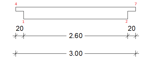
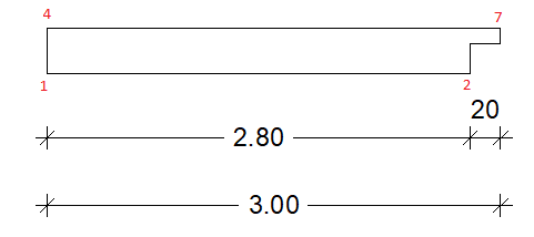
Example
The following example shows a PythonPart element with possible recesses at the left and right side. The docking point keys are represented by a unique name of the element and the point index, as shown below. The number of docking points is reduced to the docking points that are still present in the case where a recess is missing. This allows to adjust the dimension lines in case of a missing recess:
Example on GitHub
The complete implementation of creating docking points is shown in the example DockingPoints ( PYP | PY).
To evaluate the functionality of the docking points, perform following steps:
- start ALLPLAN and create a DockingPoints PythonPart
- create associative dimension lines using the docking points of the PythonPart
- change the created PythonPart by modifying the size, number of elements or by disabling the recesses
- see, how the associative dimension lines are adjusted
Plane connection
Planes in ALLPLAN can represent e.g. the top or bottom of a floor ina building. A PythonPart can refer to these planes, meaning that modifying a plane will result in the PythonPart to adapt automatically.
A reference to a plane is represented by a PlaneReferences object. You can add a parameter of this type to your .pyp file (learn how). Then, in your script, access the object like any other parameter:
Now, you can read the bottom elevation and the height of the current floor from plane_ref to create
a geometrical element that fits into the floor:
cuboid_geo = AllplanGeo.Polyhedron3D.CreateCuboid(
    build_ele.Width.value,
    build_ele.Depth.value,
    plane_ref.Height   #(1)!
    )
cuboid_geo = AllplanGeo.Move(
    cuboid_geo,
    AllplanGeo.Vector3D(0, 0, plane_ref.AbsBottomElevation) #(2)!
    )
- Create a cuboid with height equal to the floor height
- Move the cuboid so that its bottom matches the bottom of the floor
Warning
When the planes are changed by the user in ALLPLAN's floor manager, all PythonParts having this type of parameter are checked and recalculated, so
prepare your PythonPart for being updated!.
Do this by making sure, that reactivating your PythonPart with double-click and hitting Esc directly afterwards leads to a clean script termination. Otherwise, ALLPLAN can get stuck during the update.
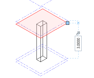
Surface planes
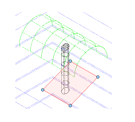
The referred plane is usually horizontal and have constant elevation. But it also can be sloped flat plane (like the red one on the image to the right) or arbitrary (the green one). If you want your PythonPart to adapt also to this kind of planes, you need to read their geometry, and these can by of type:
- Plane3D
- Polyhedron3D or
- BRep3D or
Use the BottomTopPlaneService
to get the underlying PlaneReferences object,
like: